7: Antenna Tuner Board
PRC1099A-MS
7-5
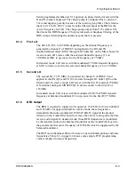
Comparator U1B compares the current detector voltage to the reference level
and sends the value back to the processor. The processor uses that value to
determine the current peak that corresponds to the lowest level VSWR.
7.1.12
D/A Decoder
The processor can only recognize a high or low output, so it is necessary to
provide a reference level to comparator U1B to measure the analog output
from the current detector. The output from the decoder is controlled by the
processor and is quantised into 64 steps. The binary steps are selected by
switching R12 through R17. Switching R7 and R8 controls the gain of
amplifier U1A.
7.1.13
Serial Decoder
Serial decoders U3A and U4A translate the serial data from the processor to
16 different outputs controlling the relay drivers that switch the various
inductors or capacitors in or out of the RF path to or from the antenna.
7.1.14
Relay Drivers
Relay drivers U5, and U6 are 16 NPN transistors contained in two 16-pin DIP
packages. There are 14 latching relays in the tuner that have separate coils for
latching and unlatching the relay. The relays require short current pulses for
latching or unlatching and draw no current in the static condition. Separate
drivers latch each relay, while transistor Q1, driven by output Q8 of U3A,
unlatches all relays. The processor always unlatches all relays before each
switching operation and resets those latched relays that require no change of
state, as well as those relays requiring switching. No separate drivers are
required to unlatch each relay.
The Antenna Tuner switches between transmit and receive operation using the
T/R relay that switches the antenna input between the receiver input and the
transmitter output. A second pole on this relay switches the regulated 8V line
to provide T8 and R8 voltage outputs. These control lines switch the
transceiver circuitry. Transistor and diode gates are used extensively for the
switching function. The input to the double-balanced mixer is switched by a
relay to minimize high level intermodulation distortion.
Содержание PRC1099A
Страница 4: ......
Страница 8: ......
Страница 35: ......
Страница 49: ...3 Audio Filter Board 3 14 PRC1099A MS Figure 3 2 Audio Filter Board Component Locations 738221 Rev J ...
Страница 65: ......
Страница 71: ...4 1650 kHz IF Board 4 6 PRC1099A MS Figure 4 2 1650 kHz IF Board Component Locations 738028 Rev D ...
Страница 76: ......
Страница 86: ...5 Mixer Board 5 10 PRC1099A MS Figure 5 4 Mixer Board Component Locations 738217 Rev H ...
Страница 97: ......
Страница 103: ...6 Power Amplifier Board 6 6 PRC1099A MS Figure 6 2 Power Amplifier Board Component Locations 738617 Rev C ...
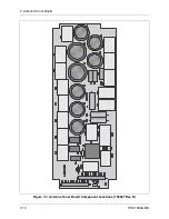
Страница 117: ...7 Antenna Tuner Board PRC1099A MS 7 9 Figure 7 2 Antenna Tuner Driver Board Component Locations 738346 Rev B ...
Страница 118: ...7 Antenna Tuner Board 7 10 PRC1099A MS Figure 7 3 Antenna Tuner Board Component Locations 738027 Rev D ...
Страница 125: ......
Страница 131: ...8 Synthesizer Board 8 6 PRC1099A MS Figure 8 2 Synthesizer Board Component Locations 738025 Rev A ...
Страница 163: ...9 Processor Board 9 14 PRC1099A MS Figure 9 2 Processor Board Component Locations 738218 Rev B ...
Страница 178: ...10 Display Board 10 8 PRC1099A MS Figure 10 1 Display Board Component Location Diagram 738220 Rev G ...
Страница 181: ......
Страница 185: ...11 Junction Board 11 4 PRC1099A MS Figure 11 1 Junction Board Component Locations 738222 Rev F ...
Страница 200: ......
Страница 207: ...13 Internal Options PRC1099A MS 13 7 Figure 13 3 ALE Board Component Locations 1 of 2 738215 Rev B ...
Страница 208: ...13 Internal Options 13 8 PRC1099A MS Figure 13 4 ALE Board Component Locations 2 of 2 738215 Rev B ...
Страница 241: ......
Страница 247: ...Index 6 T Technical specifications 1 2 Transmit path 2 4 U USB 1 4 see also Modulation modes USB LSB mode V VSWR 1 4 ...


