7: Antenna Tuner Board
7-4
PRC1099A-MS
7.1.7
Series Capacitor
Series capacitor C5 is connected between the antenna terminal and the largest
binary inductor, L10. The tuning program switches C5 in and out of the
network using relay K17 in instances where the antenna impedance is near
resonance. It rotates the impedance to a value that can be matched by the rest
of the network.
7.1.8
Current Detector
The current detector uses a saturated transformer directly in line with the
series inductors. Transformer T1 is a ferrite toroid with a single-turn primary
winding and a multi-turn secondary winding virtually shorted by 47 ohm
resistor R4. The detector output is a voltage that is proportional to the current
flowing in the primary winding. The RF voltage is rectified using diode D1.
7.1.9
Impedance Transformer
Impedance transformer T2 is a 2:1 ferrite balun switched using relays K13 and
K14. The transformer can be switched out of circuit to provide a 50 ohm
match. It can also act as a step-up transformer for a 200 ohm match and as a
step-down transformer for a 12.5 ohm match. With these three impedances
available, the transformer provides a match of 2:1 or better over the
impedance range of 6 ohms to 400 ohms.
7.1.10
10 dB Attenuator
Relay K15 switches attenuator pad R1, R2, and R3 (9.5 dB) into the tuning
circuit during a tuning cycle. The transmitter operates in low power mode
(5W) during the tune cycle; the attenuator further reduces the output power to
500 mW. The resistive pad ensures that the transmitter has a true output
impedance of 50 ohms, so that maximum output is with a 50 ohm load (a
conjugate match); maximum output current to the antenna corresponds with
minimum VSWR.
7.1.11
Comparator
Comparator U1B is the heart of the element selection circuitry. It compares
the output from current detector T1 through amplifier U1A to the reference
level from digital-to-analog convertor U2A through amplifier U1C.
The output from the current detector is divided by voltage divider R5 and
R30, amplified, and applied to the non-inverting input of amplifier U1A.
Switches Q2 and Q3 switch R7 and R8 to ground, giving three different gain
levels set by the ratio of R21 to R6, R7, or R8. This lowers the gain of
comparator U1B as the voltage from the current detector increases.
Amplifier U1C amplifies the reference level set by digital-to-analog converter
U2A through resistors R12 through R17 and applies it to the non-inverting
input of U1C.
Содержание PRC1099A
Страница 4: ......
Страница 8: ......
Страница 35: ......
Страница 49: ...3 Audio Filter Board 3 14 PRC1099A MS Figure 3 2 Audio Filter Board Component Locations 738221 Rev J ...
Страница 65: ......
Страница 71: ...4 1650 kHz IF Board 4 6 PRC1099A MS Figure 4 2 1650 kHz IF Board Component Locations 738028 Rev D ...
Страница 76: ......
Страница 86: ...5 Mixer Board 5 10 PRC1099A MS Figure 5 4 Mixer Board Component Locations 738217 Rev H ...
Страница 97: ......
Страница 103: ...6 Power Amplifier Board 6 6 PRC1099A MS Figure 6 2 Power Amplifier Board Component Locations 738617 Rev C ...
Страница 117: ...7 Antenna Tuner Board PRC1099A MS 7 9 Figure 7 2 Antenna Tuner Driver Board Component Locations 738346 Rev B ...
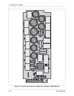
Страница 118: ...7 Antenna Tuner Board 7 10 PRC1099A MS Figure 7 3 Antenna Tuner Board Component Locations 738027 Rev D ...
Страница 125: ......
Страница 131: ...8 Synthesizer Board 8 6 PRC1099A MS Figure 8 2 Synthesizer Board Component Locations 738025 Rev A ...
Страница 163: ...9 Processor Board 9 14 PRC1099A MS Figure 9 2 Processor Board Component Locations 738218 Rev B ...
Страница 178: ...10 Display Board 10 8 PRC1099A MS Figure 10 1 Display Board Component Location Diagram 738220 Rev G ...
Страница 181: ......
Страница 185: ...11 Junction Board 11 4 PRC1099A MS Figure 11 1 Junction Board Component Locations 738222 Rev F ...
Страница 200: ......
Страница 207: ...13 Internal Options PRC1099A MS 13 7 Figure 13 3 ALE Board Component Locations 1 of 2 738215 Rev B ...
Страница 208: ...13 Internal Options 13 8 PRC1099A MS Figure 13 4 ALE Board Component Locations 2 of 2 738215 Rev B ...
Страница 241: ......
Страница 247: ...Index 6 T Technical specifications 1 2 Transmit path 2 4 U USB 1 4 see also Modulation modes USB LSB mode V VSWR 1 4 ...


