PRC1099A-MS
10-1
Chapter 10: Display Board
10.1
Circuit Description
The Display board includes the LCD, the display driver, and the backlight
generator. It also acts as a connection point connecting the Processor board to
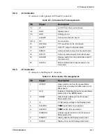
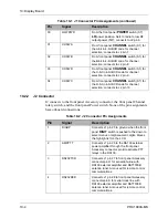
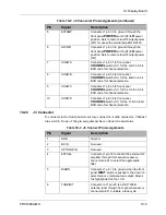
the front panel switches as well as the Accessory and Audio connectors.
10.1.1
Display
The custom LCD display provides eight, 14-segment alphanumeric characters
as well as 12 custom icons. The display also has up/down and left/right
indicators for menu navigation. The display is driven by PCF8576 CMOS LCD
driver U1, capable of driving up to 40 segments with four backplanes. The
display driver has an internal clock running at 189 kHz as determined by R1.
The data is delivered to the display driver to and from the processor through the
DISDATA line with the clock delivered on the DISCLOCK line. The display
contrast control is provided through the CONTRAST line from the Audio/Filter
board.
10.1.2
Backlight Generator
The LCD is backlit by an electroluminescent display on the backplane. The
signal that drives the backplane is generated from display driver U1 internal
clock signal. This 189 kHz clock signal is divided by 256 by counter/divider
U3, to give approximately 738 Hz to drive the backplane.
The backplane is energized when the NPN bipolar transistor Q2 emitter is
grounded through Q1, saturating the transistor. The LITE signal from the
processor transitions high, turning on Q1 which pulls the Q2 emitter to ground.
The FPLITE line from the front panel
Mode
switch can also pull the Q2 emitter
to ground when
LITE
is selected. It is grounded through the
Mode
switch center
conductor.
Once Q2 is turned on, the square wave signal from U3 is applied to step-up auto
transformer T1. The output of T1 is approximately 150 Vpp, and is used to
power the backlight.
Содержание PRC1099A
Страница 4: ......
Страница 8: ......
Страница 35: ......
Страница 49: ...3 Audio Filter Board 3 14 PRC1099A MS Figure 3 2 Audio Filter Board Component Locations 738221 Rev J ...
Страница 65: ......
Страница 71: ...4 1650 kHz IF Board 4 6 PRC1099A MS Figure 4 2 1650 kHz IF Board Component Locations 738028 Rev D ...
Страница 76: ......
Страница 86: ...5 Mixer Board 5 10 PRC1099A MS Figure 5 4 Mixer Board Component Locations 738217 Rev H ...
Страница 97: ......
Страница 103: ...6 Power Amplifier Board 6 6 PRC1099A MS Figure 6 2 Power Amplifier Board Component Locations 738617 Rev C ...
Страница 117: ...7 Antenna Tuner Board PRC1099A MS 7 9 Figure 7 2 Antenna Tuner Driver Board Component Locations 738346 Rev B ...
Страница 118: ...7 Antenna Tuner Board 7 10 PRC1099A MS Figure 7 3 Antenna Tuner Board Component Locations 738027 Rev D ...
Страница 125: ......
Страница 131: ...8 Synthesizer Board 8 6 PRC1099A MS Figure 8 2 Synthesizer Board Component Locations 738025 Rev A ...
Страница 163: ...9 Processor Board 9 14 PRC1099A MS Figure 9 2 Processor Board Component Locations 738218 Rev B ...
Страница 178: ...10 Display Board 10 8 PRC1099A MS Figure 10 1 Display Board Component Location Diagram 738220 Rev G ...
Страница 181: ......
Страница 185: ...11 Junction Board 11 4 PRC1099A MS Figure 11 1 Junction Board Component Locations 738222 Rev F ...
Страница 200: ......
Страница 207: ...13 Internal Options PRC1099A MS 13 7 Figure 13 3 ALE Board Component Locations 1 of 2 738215 Rev B ...
Страница 208: ...13 Internal Options 13 8 PRC1099A MS Figure 13 4 ALE Board Component Locations 2 of 2 738215 Rev B ...
Страница 241: ......
Страница 247: ...Index 6 T Technical specifications 1 2 Transmit path 2 4 U USB 1 4 see also Modulation modes USB LSB mode V VSWR 1 4 ...


