8: Synthesizer Board
PRC1099A-MS
8-3
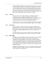
Serial-programmed synthesizer U18 operates in phase detector mode with the
R and N counters bypassed. The charge pump is configured for a current of
5 mA and negative polarity because of the inverting loop filter. The reference
input to U18 (LO1_OUT) comes from the filtered output of the DDS at the
correct frequency for LO1. The charge pump output from U18 controls U16
that tracks the DDS frequency. This provides narrow bandpass filtering of the
DDS output, eliminating the numerous spurs that are present.
8.1.4
First LO
The first LO (76.6 to 105 MHz depending on the channel frequency) is
generated by channel 1 of DDS U9 and applied to the RX and TX
double-balanced mixer (MX1) through LO1 buffer Q1 on the Mixer board. In
receive mode, LO1 mixes with the selected channel frequency (1.6 to
30 MHz) at MX1 to up-convert to the IF frequency of 75 MHz.
In transmit mode, LO1 mixes with the modulated 75 MHz transmit frequency
at MX1 to down-convert to the selected channel frequency (1.6 to 30 MHz).
8.1.5
Second LO
The second LO (73.35 MHz) is generated by channel 0 of DDS U9 and
applied to the RX (Q8) and TX (U2) mixers through LO2 buffer Q10 on the
Mixer board. In receive mode, LO2 mixes with the first IF (nominal 75 MHz)
at N-channel, dual-gate MOSFET Q8 to down-convert to the final IF of
1650 kHz.
In transmit mode, LO1 mixes with the modulated 1650/1647 MHz transmit
frequency at balanced modulator U2 to up-convert to the first IF (75 MHz).
8.1.6
BFO Output
The BFO is required to supply two frequencies, 1647 kHz for lower sideband
and 1650 kHz for upper sideband. In receive mode, these frequencies
demodulate the audio-modulated 1650/1647 kHz IF signal in the product
detector on the Audio/Filter board to remove the carrier, leaving only the base
receive audio signal. In transmit mode, these BFO frequencies is modulated
by the transmit audio in the balanced modulator on the Audio/Filter board to
the generate the first carrier frequency of 1650 kHz which is suppressed by the
balanced modulator.
The BFO is also bandpass filtered to remove any wideband spurious and noise
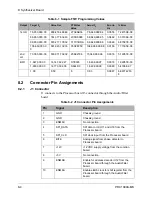
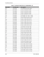
frequencies. Table 8-1 on page 8-4 shows some sample FTW programming
values compared to target frequencies.
Содержание PRC1099A
Страница 4: ......
Страница 8: ......
Страница 35: ......
Страница 49: ...3 Audio Filter Board 3 14 PRC1099A MS Figure 3 2 Audio Filter Board Component Locations 738221 Rev J ...
Страница 65: ......
Страница 71: ...4 1650 kHz IF Board 4 6 PRC1099A MS Figure 4 2 1650 kHz IF Board Component Locations 738028 Rev D ...
Страница 76: ......
Страница 86: ...5 Mixer Board 5 10 PRC1099A MS Figure 5 4 Mixer Board Component Locations 738217 Rev H ...
Страница 97: ......
Страница 103: ...6 Power Amplifier Board 6 6 PRC1099A MS Figure 6 2 Power Amplifier Board Component Locations 738617 Rev C ...
Страница 117: ...7 Antenna Tuner Board PRC1099A MS 7 9 Figure 7 2 Antenna Tuner Driver Board Component Locations 738346 Rev B ...
Страница 118: ...7 Antenna Tuner Board 7 10 PRC1099A MS Figure 7 3 Antenna Tuner Board Component Locations 738027 Rev D ...
Страница 125: ......
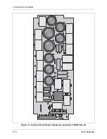
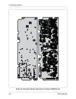
Страница 131: ...8 Synthesizer Board 8 6 PRC1099A MS Figure 8 2 Synthesizer Board Component Locations 738025 Rev A ...
Страница 163: ...9 Processor Board 9 14 PRC1099A MS Figure 9 2 Processor Board Component Locations 738218 Rev B ...
Страница 178: ...10 Display Board 10 8 PRC1099A MS Figure 10 1 Display Board Component Location Diagram 738220 Rev G ...
Страница 181: ......
Страница 185: ...11 Junction Board 11 4 PRC1099A MS Figure 11 1 Junction Board Component Locations 738222 Rev F ...
Страница 200: ......
Страница 207: ...13 Internal Options PRC1099A MS 13 7 Figure 13 3 ALE Board Component Locations 1 of 2 738215 Rev B ...
Страница 208: ...13 Internal Options 13 8 PRC1099A MS Figure 13 4 ALE Board Component Locations 2 of 2 738215 Rev B ...
Страница 241: ......
Страница 247: ...Index 6 T Technical specifications 1 2 Transmit path 2 4 U USB 1 4 see also Modulation modes USB LSB mode V VSWR 1 4 ...


