13: Internal Options
PRC1099A-MS
13-3
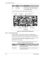
P3 ports provide the following high priority interrupt functions:
The ALE, PSEN, RD, WR, address/data lines AD0-AD7 and data lines
A8-A15 communicate with the external EPROM, RAM, EEPROM, and DSP
processor.
Reset Controller
Reset controller U1 provides three functions. The first function is a reset pulse
generator that monitors the +5V line. It generates a reset output to hold the
processor’s reset line low whenever the +5V line is below 4.5 VDC. On power
up, an internal monostable multivibrator circuit holds the reset line low for
250 ms, allowing the power supply to stabilize before generating the reset
pulse. This also prevents the reset line from toggling repeatedly.
The second function provides a debounced reset-input line for an external
push button to reset the processor. It is available on J1 pin 7.
The third function of U1 is a processor watchdog that requires the processor to
toggle the STB input at least once every 500 ms. If the processor fails to do so,
the reset controller assumes that it has locked up and provides a reset pulse to
reset the processor. This function is primarily for firmware development; the
ALE card is able to recover from it without any external help.
Clock Oscillator
Clock oscillator U2 (11.0592 MHz) provides the internal clock for main ALE
processor U1. Clock oscillator U12 is a high-stability oscillator (20.48 MHz)
providing the internal clock and timing for the DSP processor.
Buffers
Inverter/buffer chip U22 protects the main ALE processor from the outside
world. Outputs U22D and U22C buffer the serial control interface. Outputs
U22E and U22F buffer the PTT input and output.
Program Storage
EPROM chip U80 stores the main firmware operating program for the ALE
card. DSP EPROM chips U94 and U98 store the high-speed DSP firmware.
RAM chip U5 stores all the current operating data. DSP RAM chips U14 and
U15 execute the high-speed DSP software.
EEPROM chips U6 and U7 are non-volatile memory devices that store long
term operating data and parameters.
Memory Backup
Capacitor C10 provides backup power to RAM chip U5. It only provides a
few days of reserve power for RAM memory.
Port
Function
P3.1
Transmit driver pin for the serial control interface.
P3.2
Receive driver pin for the serial control interface.
P3.3
Interrupt from the dual port RAM that indicates the DSP has
left data for it to retrieve and process.
P3.4, 5
External timing inputs from the DSP processor.
Содержание PRC1099A
Страница 4: ......
Страница 8: ......
Страница 35: ......
Страница 49: ...3 Audio Filter Board 3 14 PRC1099A MS Figure 3 2 Audio Filter Board Component Locations 738221 Rev J ...
Страница 65: ......
Страница 71: ...4 1650 kHz IF Board 4 6 PRC1099A MS Figure 4 2 1650 kHz IF Board Component Locations 738028 Rev D ...
Страница 76: ......
Страница 86: ...5 Mixer Board 5 10 PRC1099A MS Figure 5 4 Mixer Board Component Locations 738217 Rev H ...
Страница 97: ......
Страница 103: ...6 Power Amplifier Board 6 6 PRC1099A MS Figure 6 2 Power Amplifier Board Component Locations 738617 Rev C ...
Страница 117: ...7 Antenna Tuner Board PRC1099A MS 7 9 Figure 7 2 Antenna Tuner Driver Board Component Locations 738346 Rev B ...
Страница 118: ...7 Antenna Tuner Board 7 10 PRC1099A MS Figure 7 3 Antenna Tuner Board Component Locations 738027 Rev D ...
Страница 125: ......
Страница 131: ...8 Synthesizer Board 8 6 PRC1099A MS Figure 8 2 Synthesizer Board Component Locations 738025 Rev A ...
Страница 163: ...9 Processor Board 9 14 PRC1099A MS Figure 9 2 Processor Board Component Locations 738218 Rev B ...
Страница 178: ...10 Display Board 10 8 PRC1099A MS Figure 10 1 Display Board Component Location Diagram 738220 Rev G ...
Страница 181: ......
Страница 185: ...11 Junction Board 11 4 PRC1099A MS Figure 11 1 Junction Board Component Locations 738222 Rev F ...
Страница 200: ......
Страница 207: ...13 Internal Options PRC1099A MS 13 7 Figure 13 3 ALE Board Component Locations 1 of 2 738215 Rev B ...
Страница 208: ...13 Internal Options 13 8 PRC1099A MS Figure 13 4 ALE Board Component Locations 2 of 2 738215 Rev B ...
Страница 241: ......
Страница 247: ...Index 6 T Technical specifications 1 2 Transmit path 2 4 U USB 1 4 see also Modulation modes USB LSB mode V VSWR 1 4 ...


