PRC1099A-MS
11-1
Chapter 11: Junction Board
11.1
Circuit Description
The Junction board supplies DC power to the radio; it also acts as a junction
point for board interconnects. The Junction board includes the +5 VDC and
+8 VDC regulators as well as clamps for the R8 and T8 lines.
11.1.1
+5V Supply
The Junction board provides the +5V supply voltage that supplies power for the
entire transceiver. DC to DC switching voltage converter U1 converts the +12V
input voltage to +5 VDC. Resistor R1 limits the +5V supply to a maximum
current of approximately 700 mA. The output of the converter is heavily
filtered by L1, L4, C2 to C4, and C17 to reduce the voltage ripple of the
converter to less than 20 mVpp. Trimmer resistor R4 sets the converter output
which is measured at TP3. Poly resistor PF1 and diode D3 provide protection
against voltage converter U1 failure.
11.1.2
+8V Supply
Regulator U2 converts the +12 VDC input voltage to provide the +8V supply. It
includes an internal thermal overload protection that allows the output to short
circuit without damaging the device. The output voltage is filtered by C6, C10,
C13, and L5 to remove any residual ripple. Trimmer resistor R5 sets the
+8 VDC output which is measured at TP2.
11.1.3
DC Clamps
The Junction board also includes the R8 and T8 DC clamps. These clamps, Q1
and Q2, are alternately energized by either R8 or T8.
In transmit mode, the T8 line energizes Q1, clamping the R8 line to ground; in
receive mode, the R8 line energizes Q2, clamping the T8 line to ground.
Switching between T8 and R8 is instantaneous.
Содержание PRC1099A
Страница 4: ......
Страница 8: ......
Страница 35: ......
Страница 49: ...3 Audio Filter Board 3 14 PRC1099A MS Figure 3 2 Audio Filter Board Component Locations 738221 Rev J ...
Страница 65: ......
Страница 71: ...4 1650 kHz IF Board 4 6 PRC1099A MS Figure 4 2 1650 kHz IF Board Component Locations 738028 Rev D ...
Страница 76: ......
Страница 86: ...5 Mixer Board 5 10 PRC1099A MS Figure 5 4 Mixer Board Component Locations 738217 Rev H ...
Страница 97: ......
Страница 103: ...6 Power Amplifier Board 6 6 PRC1099A MS Figure 6 2 Power Amplifier Board Component Locations 738617 Rev C ...
Страница 117: ...7 Antenna Tuner Board PRC1099A MS 7 9 Figure 7 2 Antenna Tuner Driver Board Component Locations 738346 Rev B ...
Страница 118: ...7 Antenna Tuner Board 7 10 PRC1099A MS Figure 7 3 Antenna Tuner Board Component Locations 738027 Rev D ...
Страница 125: ......
Страница 131: ...8 Synthesizer Board 8 6 PRC1099A MS Figure 8 2 Synthesizer Board Component Locations 738025 Rev A ...
Страница 163: ...9 Processor Board 9 14 PRC1099A MS Figure 9 2 Processor Board Component Locations 738218 Rev B ...
Страница 178: ...10 Display Board 10 8 PRC1099A MS Figure 10 1 Display Board Component Location Diagram 738220 Rev G ...
Страница 181: ......
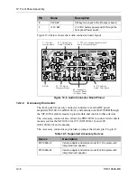
Страница 185: ...11 Junction Board 11 4 PRC1099A MS Figure 11 1 Junction Board Component Locations 738222 Rev F ...
Страница 200: ......
Страница 207: ...13 Internal Options PRC1099A MS 13 7 Figure 13 3 ALE Board Component Locations 1 of 2 738215 Rev B ...
Страница 208: ...13 Internal Options 13 8 PRC1099A MS Figure 13 4 ALE Board Component Locations 2 of 2 738215 Rev B ...
Страница 241: ......
Страница 247: ...Index 6 T Technical specifications 1 2 Transmit path 2 4 U USB 1 4 see also Modulation modes USB LSB mode V VSWR 1 4 ...


