14: Maintenance
PRC1099A-MS
14-13
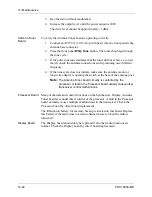
5. Remove the top two screws on either side of the front panel flange as
shown below.
6. Loosen the bottom two screws; do not remove them.
7. Tilt the front panel forward to gain access to the Display board.
8. Tighten the bottom screws again to keep the front panel in place.
9. Disconnect the three connectors and remove the four mounting screws
and the board.
10. Lift the Display board off the front panel assembly.
11. Reverse this procedure to install the new Display board.
Remove and
Replace the
Junction Board
To remove and replace the Junction board:
1. Disassemble radio chassis (refer to “Chassis Disassembly” on page
2. Remove the 1650 kHz IF board (refer to “Remove and Replace the
1650 kHz IF Board” on page 14-7).
3. Disconnect the three connectors (J1, J2, and J3).
4. Unsolder the two wires from the battery connector.
5. Remove the four mounting screws and the board and lift the board out
of the chassis.
6. Reverse this procedure to install the new Function board.
Remove and
Replace the
Front Panel
Assembly
To remove and replace the Front Panel assembly:
1. Disassemble the radio chassis (refer to “Chassis Disassembly” on page
2. Remove the Mixer/Synthesizer tray (refer to “Remove and Replace the
Processor Board” on page 14-11, steps 2 and 3).
Remove
Tilt
Display Board
Flange
Содержание PRC1099A
Страница 4: ......
Страница 8: ......
Страница 35: ......
Страница 49: ...3 Audio Filter Board 3 14 PRC1099A MS Figure 3 2 Audio Filter Board Component Locations 738221 Rev J ...
Страница 65: ......
Страница 71: ...4 1650 kHz IF Board 4 6 PRC1099A MS Figure 4 2 1650 kHz IF Board Component Locations 738028 Rev D ...
Страница 76: ......
Страница 86: ...5 Mixer Board 5 10 PRC1099A MS Figure 5 4 Mixer Board Component Locations 738217 Rev H ...
Страница 97: ......
Страница 103: ...6 Power Amplifier Board 6 6 PRC1099A MS Figure 6 2 Power Amplifier Board Component Locations 738617 Rev C ...
Страница 117: ...7 Antenna Tuner Board PRC1099A MS 7 9 Figure 7 2 Antenna Tuner Driver Board Component Locations 738346 Rev B ...
Страница 118: ...7 Antenna Tuner Board 7 10 PRC1099A MS Figure 7 3 Antenna Tuner Board Component Locations 738027 Rev D ...
Страница 125: ......
Страница 131: ...8 Synthesizer Board 8 6 PRC1099A MS Figure 8 2 Synthesizer Board Component Locations 738025 Rev A ...
Страница 163: ...9 Processor Board 9 14 PRC1099A MS Figure 9 2 Processor Board Component Locations 738218 Rev B ...
Страница 178: ...10 Display Board 10 8 PRC1099A MS Figure 10 1 Display Board Component Location Diagram 738220 Rev G ...
Страница 181: ......
Страница 185: ...11 Junction Board 11 4 PRC1099A MS Figure 11 1 Junction Board Component Locations 738222 Rev F ...
Страница 200: ......
Страница 207: ...13 Internal Options PRC1099A MS 13 7 Figure 13 3 ALE Board Component Locations 1 of 2 738215 Rev B ...
Страница 208: ...13 Internal Options 13 8 PRC1099A MS Figure 13 4 ALE Board Component Locations 2 of 2 738215 Rev B ...
Страница 241: ......
Страница 247: ...Index 6 T Technical specifications 1 2 Transmit path 2 4 U USB 1 4 see also Modulation modes USB LSB mode V VSWR 1 4 ...


