RAPID CONFIGURATION
5
1
STEP 2
– MOUNT AND POSITION THE READER
1.
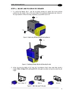
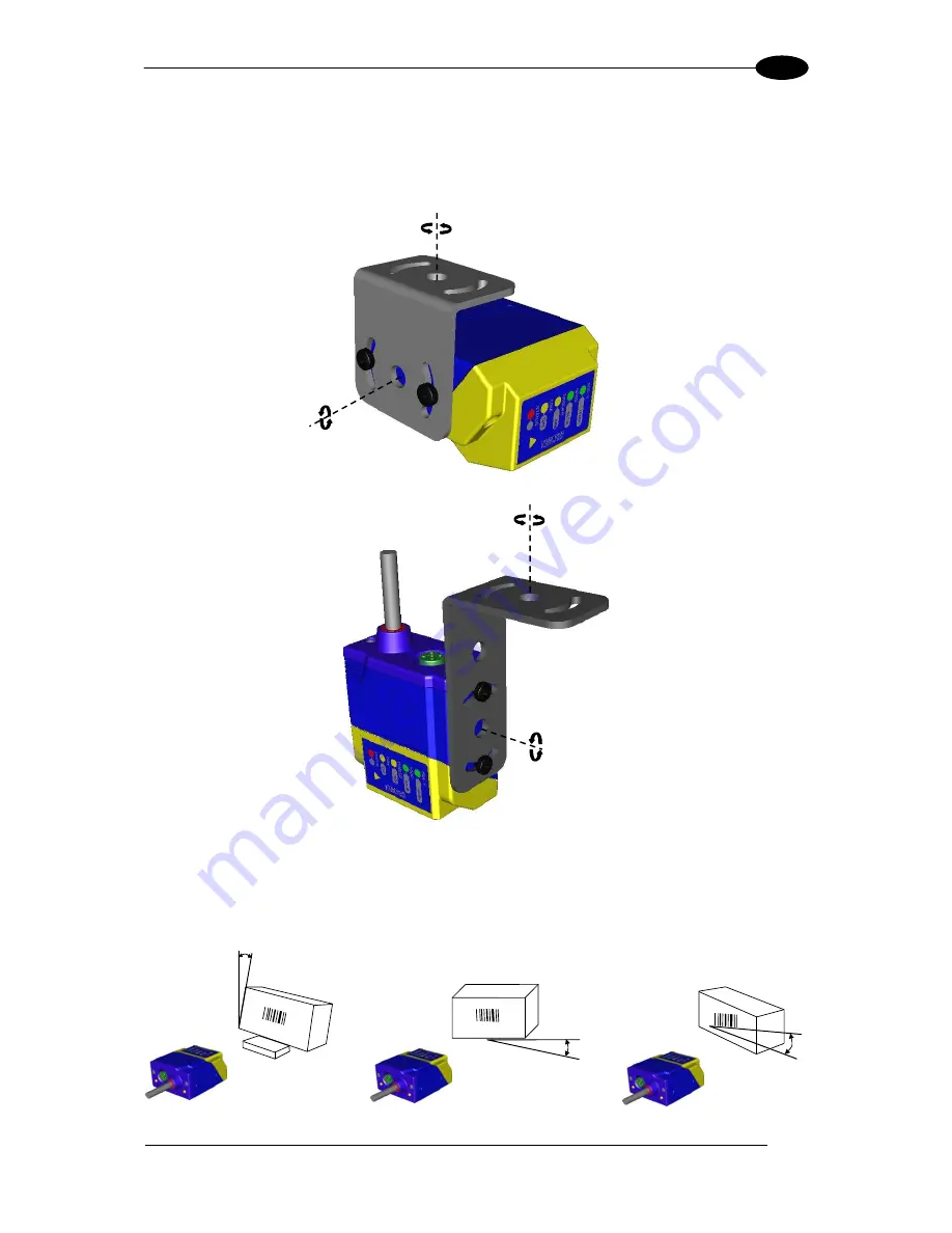
To mount the Matrix 210™, use the mounting brackets to obtain the most suitable
position for the reader. Two of the most common mounting configurations are shown in
the figures below. Other mounting solutions are provided in par. 3.3.
Figure 3
–Positioning 90° Model with Mounting Bracket
Figure 4
–Positioning Straight Model with Mounting Bracket
2.
When mounting the Matrix 210™ take into consideration these three ideal label position
angles:
Pitch or Skew 10° to 20° and Tilt 0°
, although the reader can read a code at any tilt
angle.
P
S
T
Assure at least 10°
Minimize
Minimize
Figure 5
– Pitch, Skew and Tilt Angles
Tilt
Pitch
Tilt
Pitch
Содержание Matrix 210
Страница 1: ...MATRIX 210 Reference Manual...
Страница 59: ...CBX ELECTRICAL CONNECTIONS 49 4 Figure 45 ID NET Network Connections with isolated power blocks...
Страница 60: ...MATRIX 210 REFERENCE MANUAL 50 4 Figure 46 ID NET Network Connections with Common Power Branch Network...
Страница 61: ...CBX ELECTRICAL CONNECTIONS 51 4 Figure 47 ID NET Network Connections with Common Power Star Network...
Страница 78: ...MATRIX 210 REFERENCE MANUAL 68 5 Figure 71 ID NET Network Connections with isolated power blocks...
Страница 79: ...25 PIN CABLE ELECTRICAL CONNECTIONS 69 5 Figure 72 ID NET Network Connections with Common Power Branch Network...
Страница 80: ...MATRIX 210 REFERENCE MANUAL 70 5 Figure 73 ID NET Network Connections with Common Power Star Network...
Страница 111: ...SOFTWARE CONFIGURATION 101 8 Figure 111 Options Communication Figure 112 Options Communication Ethernet...
Страница 142: ...www datalogic com...

