background image

SOFTWARE CONFIGURATION 


101 


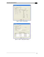
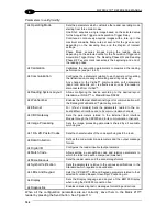
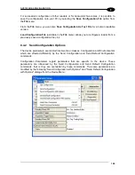
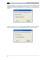
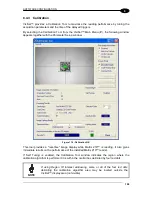
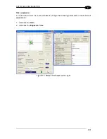
Figure 111 - Options 

– Communication 


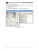
Figure 112 - Options 

– Communication: Ethernet 


Содержание Matrix 210

Страница 1: ...MATRIX 210 Reference Manual...

Страница 2: ...alogic and the Datalogic logo are registered trademarks of Datalogic S p A in many countries including the U S A and the E U Matrix 210 ID NET VisiSet and X PRESS are trademarks of Datalogic Automatio...

Страница 3: ...nfiguration 14 2 INTRODUCTION 15 2 1 Product Description 15 2 2 Indicators and Keypad Button 18 2 3 ID NET 19 2 3 1 How To Setup Configure the Reader Network 20 2 3 2 ID NET Slave Management Through M...

Страница 4: ...RS485 Full Duplex Interface 63 5 4 3 RS485 Half Duplex Interface 64 5 5 ID NET Interface 66 5 5 1 ID NET Cables 66 5 5 2 ID NET Response Time 67 5 5 3 ID NET Network Termination 71 5 6 Auxiliary RS232...

Страница 5: ...4 5 Run Time Self Tuning RTST 113 8 4 6 Region Of Interest Windowing 114 8 4 7 Direct Part Marking Applications 115 8 5 Image Capture and Decoding 120 8 6 Statistics 120 9 MAINTENANCE 121 9 1 Cleanin...

Страница 6: ...tion Products Industrial Automation Identification Select your product from the links on the Identification page The product page describes specific Info Features Applications Models Accessories and D...

Страница 7: ...a domestic environment this product may cause radio interference in which case the user may be required to take adequate measures FCC COMPLIANCE Modifications or changes to this equipment without the...

Страница 8: ...and vibration and shock when correctly installed however it is also a precision product and therefore before and during installation it must be handled correctly to avoid damage avoid that the readers...

Страница 9: ...ix do not weld the reader into position which can cause electrostatic heat or reading window damage do not spray paint near the reader which can cause reading window damage...

Страница 10: ...x GENERAL VIEW Matrix 210 Figure A Mounting Holes 4 Ethernet Network Presence LED for Ethernet Models 1 3 Power ON LED 2 HMI X PRESS Interface 4 Reading Window 5 Device Class Labels 6 3 5 4 1 6 2 1...

Страница 11: ...serial interface Data can also be transmitted on the RS232 auxiliary interface independently from the main interface selection When One Shot or Phase Mode Operating mode is used the reader is activate...

Страница 12: ...y Interface I1B External Trigger B polarity insensitive TX Auxiliary Interface TX V Power Reference External Trigger RX Auxiliary Interface RX V Power Source Inputs SGND Auxiliary Interface Reference...

Страница 13: ...64 DPInstx64 exe For other operating systems see the readme txt in the Support Files Software Utilities USB Virtual COM Port Drivers directory For updated drivers or more details go to ftdichip com Dr...

Страница 14: ...mber if desired optional Set the BM Options Latency Timer msec parameter to 1 You are now ready to use the new COM Port Matrix 210 USB models can be connected in a Point to Point layout to a local hos...

Страница 15: ...Other mounting solutions are provided in par 3 3 Figure 3 Positioning 90 Model with Mounting Bracket Figure 4 Positioning Straight Model with Mounting Bracket 2 When mounting the Matrix 210 take into...

Страница 16: ...e reader near the cable the POWER ON LED blue indicates the reader is correctly powered 2 Enter the Aim Locate function by pressing and holding the X PRESS push button until the Aim LED is on 3 Releas...

Страница 17: ...ing In this case Matrix 210 emits a long low pitched beep 3 Exit the Setup function by pressing the X PRESS push button once green green yellow yellow red Figure 8 X PRESS Interface Setup Function Lea...

Страница 18: ...holding the X PRESS push button pressed while powering up the reader You must keep the X PRESS push button pressed until the power up sequence is completed several seconds and all LEDs blink simultane...

Страница 19: ...allowing to consider the reader as a remote object to be configured and monitored To install VisiSet turn on the PC that will be used for the configuration running Windows 98 2000 NT XP Vista 7 or 8...

Страница 20: ...onnection STEP 6 CONFIGURATION USING SETUP WIZARD The Setup Wizard option is advised for rapid configuration or for new users It allows reader configuration in a few easy steps 1 Select the Setup Wiza...

Страница 21: ...d images which indicate the region in which the calibration algorithm is active Move the reader or code to center it Press the Positioning button again to stop positioning 3 Select a Calibration Mode...

Страница 22: ...etup Wizard window shows the code type results and the parameter settings 5 Select a Saving Options choice and press the Save button 6 Close the Setup Wizard NOTE If your application has been configur...

Страница 23: ...lease the button to enter the Test function Once entered the Bar Graph on the five LEDs is activated and if the reader starts reading codes the Bar Graph shows the Good Read Rate In case of no read co...

Страница 24: ...dow and then sent to the reader memory either Temporary or Permanent Figure 14 VisiSet Parameter Setup Window Host Mode Programming The reader can also be configured from a host computer using the Hos...

Страница 25: ...ative Optical Features The innovative optical and lighting systems ensure wide field of view at short reading distances combined with excellent illumination pattern Matrix 210 has a maximum reading di...

Страница 26: ...ion software program VisiSet provided on Mini DVD with the reader There are different programmable operating modes to suit various code reading system requirements Quick automatic positioning calibrat...

Страница 27: ...apability on 1D 2D Stacked and Postal symbologies High performance on dynamic reading applications X PRESS for easy and intuitive setup Optical Aiming System 10 to 30 VDC Power Supply High Speed Ether...

Страница 28: ...dy to operate Figure 15 3 GOOD green LED confirms successful reading Figure 15 4 TRIGGER yellow LED indicates the status of the reading phase Figure 15 5 COM yellow LED indicates active communication...

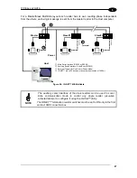
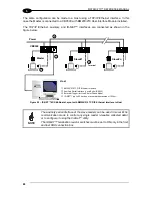
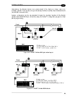
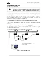
Страница 29: ...ble ID NET M S Synchronized Single station multiple readers ID NET interface allows local connection of multiple readers reading different sides of the same target All readers share a single presence...

Страница 30: ...t as follows Mounting Connection 1 Mechanically mount install all the readers refer to par 3 2 and 3 3 2 Wire ID NET refer to par 4 3 or 5 5 3 Power up the entire system Configuration of Slaves 1 Conn...

Страница 31: ...logy Role parameter 5 Enable the planned Slave device N from the Reading System Layout Expected Slave Device N Status parameter and if desired set the related identification string from the Expected S...

Страница 32: ...check the status of the expected Slave devices within the ID NET network 4 Click anywhere in the row of the specific slave in the ID NET Status Window when its Current Status is Present The Parameter...

Страница 33: ...tions are supported by VisiSet for all reading devices having sw 6 10 and later when connected to CBX BM100 and or BM2x0 sw release 2 02 01 and later QL500 Ethernet TCP IP sw release 2 02 01 and later...

Страница 34: ...the backup procedure is performed and a message indicating successful completion Restore To perform a Restore 1 Select External Memory Restore from the VisiSet Device menu 2 You will be warned that t...

Страница 35: ...completion Replacement The External Memory Restore function also provides easy and secure Single Device Replacement 1 Remove the device to be replaced 2 Connect the new device make sure the new devic...

Страница 36: ...ous Backup 1 Select External Memory Erase from the VisiSet Device menu 2 You will be warned that all device configurations in the current backup will be erased Confirm by clicking Yes The VisiSet Main...

Страница 37: ...Set main window in case of an External Memory function failure Module not present backup module not mounted BM100 or not ready QL500 BM2x0 Unable to Read Backup State VisiSet is unable to connect to t...

Страница 38: ...Time and Gain calibration Aim Locate to turn on the blue ring to aid positioning Test with bar graph visualization to check static reading performance 2 5 1 X PRESS Functions Quick access to the foll...

Страница 39: ...only the Status LED is on and blinks The Bar Graph has the following meaning 95 75 60 40 20 To exit the Test Mode press the X PRESS push button once NOTE By default the Test exits automatically after...

Страница 40: ...detect and recognize codes which are presented to it The Learn LED will blink until the procedure is completed The Learn procedure ends when the Image Processing and Decoding parameters are successful...

Страница 41: ...Modular Connection Box 93A301068 BM100 Backup Module for CBX100 500 93ACC1808 BM150 Display Module for CBX500 93ACC1809 BM200 BM210 Ethernet TCP IP Module STD IP65 for CBX500 93ACC1851 93ACC1852 BM300...

Страница 42: ...USB Hubs and have no accessories 2 8 APPLICATION EXAMPLES 2 8 1 Document Handling Matrix 210 is profitably used in the omnidirectional reading of 2D stacked linear and postal codes for example in auto...

Страница 43: ...by Matrix 210 in spite of Image Optical Distortion 2 8 3 Direct Part Marking Matrix 210 is also very powerful in reading low contrast direct part marked codes see Figures 21 22 23 24 and 25 Figure 20...

Страница 44: ...e 23 Dot Matrix Code Directly Marked on PCB Copper Pad by Using Ink Jet Technology 2 8 5 Laser Marking Etching Technology Figure 24 Data Matrix Code Directly Marked on PCB Surface by Using Laser Etchi...

Страница 45: ...applications with uneven noisy and scratched surfaces where dot peening or laser etching codes are directly marked onto metal surfaces or PCBs and need to be highlighted Here the use of more than one...

Страница 46: ...210 reader and all the parts supplied with the equipment are present and intact when opening the packaging the list of parts includes Matrix 210 reader Quick Reference Guide Test Chart Matrix family M...

Страница 47: ...sions of the reader and may be used for its installation Refer to par 3 3 for various mounting solutions and correct positioning and chp 7 for Reading Distance considerations 32 1 25 9 0 0 36 25 0 0 9...

Страница 48: ...0 98 19 0 75 60 30 12 5 0 49 25 0 98 60 30 6 2 n 3 n 4 S L O T 3 1 Figure 29 ST 336 Mounting Bracket Overall Dimensions 38 22 0 87 1 50 2 0 08 10 0 39 30 60 60 30 n 4 SLOT 3 1 6 2 n 2 10 0 39 18 5 0...

Страница 49: ...can obtain rotation on the various axes of the reader as shown in the diagrams below Figure 31 90 Model with ST 337 Mounting Bracket Internal Positioning Figure 32 Straight Model with ST 336 Mounting...

Страница 50: ...modifying the Pitch angle Follow the suggestions below for the best orientation The Pitch and Skew angles are represented by the values P and S in Figure 34 and in Figure 35 Position the reader in or...

Страница 51: ...Input Power Vdc Power Supply Input Voltage GND Power Supply Input Voltage Earth Protection Earth Ground Inputs V Power Source External Trigger I1A External Trigger A polarity insensitive I1B External...

Страница 52: ...ropriate jumper in the CBX connection box See the CBX Installation Manual for details 4 2 MAIN SERIAL INTERFACE CAUTION Do not connect to the Main Interface spring clamp terminals if using Host Interf...

Страница 53: ...erall maximum cable length must be less than 15 m 49 2 ft SGND RXD TXD CTS RTS USER INTERFACE SGND TX RX RTS CTS READER Figure 38 RS232 Main Interface Connections Using Hardware Handshaking The RTS an...

Страница 54: ...ironments The CBX pinout follows CBX100 500 Function TX RS485 Transmit Data RX RS485 Receive Data TX RS485 Transmit Data RX RS485 Receive Data SGND Signal Ground RX485 TX485 SGND RX485 TX485 USER INTE...

Страница 55: ...a master device polls slave devices to collect data CBX100 500 Function RTX RS485 Receive Transmit Data RTX RS485 Receive Transmit Data SGND Signal Ground RTX485 SGND RTX485 USER INTERFACE SGND RTX R...

Страница 56: ...UAL 46 4 Figure 43 Matrix 210 Multidrop Connection to a Multiplexer When using CBX500 the Main interface multidrop network signals Shield SGND RTX and RTX are repeated on terminal connector row 4 to f...

Страница 57: ...max cable length depends on the baudrate used see the Baudrate Table below For Common Power Connections use only 2 wires ID and ID DC Voltage Power cable Vdc GND should be handled as a signal cable i...

Страница 58: ...between the Trigger activation and the beginning of data transmission to the Host Max ID NET Response Time 240 220 200 180 160 140 120 100 80 60 40 20 0 Response Time ms Number of Nodes 500 kbps 250...

Страница 59: ...CBX ELECTRICAL CONNECTIONS 49 4 Figure 45 ID NET Network Connections with isolated power blocks...

Страница 60: ...MATRIX 210 REFERENCE MANUAL 50 4 Figure 46 ID NET Network Connections with Common Power Branch Network...

Страница 61: ...CBX ELECTRICAL CONNECTIONS 51 4 Figure 47 ID NET Network Connections with Common Power Star Network...

Страница 62: ...etc as well as particular communication modes such as LOCAL ECHO can be defined through the Communication folder of the VisiSet utility program The 9 pin female Auxiliary Interface connector inside t...

Страница 63: ...selected in software Refer to the VisiSet Help On Line An anti disturbance filter is implemented in software on both inputs so that the minimum pulse duration is 0 5 milliseconds This value can be in...

Страница 64: ...ernal Trigger Using Matrix 210 Power Power to Input Photocell Signal Photocell Reference NPN Photocell Figure 51 NPN External Trigger Using Matrix 210 Power EXTERNAL TRIGGER INPUT CONNECTIONS USING EX...

Страница 65: ...to the Input Device independently from the Power Supply Switch inside the CBX Power to Input Device Input Input Device Signal Reference Input Device PNP Input 2 Using Matrix 210 Power Power to Input...

Страница 66: ...2 O2 Output 2 V Power Reference Outputs The electrical features of the two outputs are the following VCE 30 Vdc max ICE 40 mA continuous max 130 mA pulsed max By default Output 1 is associated with t...

Страница 67: ...re 56 Open Emitter Output Using Matrix 210 Power Power to Output device Output device Reference Output Device Output Signal Figure 57 Open Collector Output Using Matrix 210 Power OUTPUT CONNECTIONS US...

Страница 68: ...must be connected as the control signal In VisiSet configure the Output Line Function parameter to External Lighting System and the Matrix Output x External Lighting System Mode parameter to Triggered...

Страница 69: ...tains the pinout for standard RS232 PC Host interface For other user interface types please refer to their own manual RS232 PC side connections 1 5 9 6 9 pin male connector 13 25 14 1 25 pin male conn...

Страница 70: ...igger A polarity insensitive 19 I1B External Trigger B polarity insensitive 6 I2A Input 2 A polarity insensitive 10 I2B Input 2 B polarity insensitive 8 O1 Output 1 22 O1 Output 1 11 O2 Output 2 12 O2...

Страница 71: ...pin connector see Figure 63 Earth Ground CHASSIS VGND V 10 30 Vdc 13 25 1 Vdc GND CHASSIS POWER SUPPLY Matrix 210 Figure 63 Power Supply Connection The allowed supply voltage range is 10 to 30 Vdc It...

Страница 72: ...o Send 5 CTS Clear To Send 7 GND Ground It is always advisable to use shielded cables The overall maximum cable length must be less than 15 m 49 2 ft Matrix 210 7 4 5 3 GND RTS CTS RX TX 2 USER INTERF...

Страница 73: ...onnector are used for RS485 full duplex communication Pin Name Function 2 TX RS485 Transmit Data 3 RX RS485 Receive Data 4 TX RS485 Transmit Data 5 RX RS485 Receive Data 7 GND Ground Matrix 210 TX 2 T...

Страница 74: ...ocol based on polled mode called MUX32 protocol where a master device polls slave devices to collect data The following pins of the 25 pin connector are used for RS485 half duplex communication Pin Na...

Страница 75: ...ow shows a multidrop configuration with Matrix 210 readers connected to a Multiplexer CAUTION This is an example of multidrop wiring Consult the multiplexer manual for complete wiring instructions Fig...

Страница 76: ...depends on the baudrate used see the Baudrate Table below For Common Power Connections use only 2 wires 23 and 24 DC Voltage Power cable Vdc GND should be handled as a signal cable i e do not put it...

Страница 77: ...riod between the Trigger activation and the beginning of data transmission to the Host Max ID NET Response Time 240 220 200 180 160 140 120 100 80 60 40 20 0 Response Time ms Number of Nodes 500 kbps...

Страница 78: ...MATRIX 210 REFERENCE MANUAL 68 5 Figure 71 ID NET Network Connections with isolated power blocks...

Страница 79: ...25 PIN CABLE ELECTRICAL CONNECTIONS 69 5 Figure 72 ID NET Network Connections with Common Power Branch Network...

Страница 80: ...MATRIX 210 REFERENCE MANUAL 70 5 Figure 73 ID NET Network Connections with Common Power Star Network...

Страница 81: ...ws both transmission of code data and reader configuration by VisiSet The parameters relative to the aux interface baud rate data bits etc as well as particular communication modes such as LOCAL ECHO...

Страница 82: ...ed Connector Pinout Pin Name Function 1 TX Transmitted data positive pin 2 RX Received data positive pin 3 TX Transmitted data negative pin 4 RX Received data negative pin MATRIX 3 4 2 1 TX RX TX RX L...

Страница 83: ...ese inputs are selected in software Refer to the VisiSet Help On Line An anti disturbance filter is implemented in software on both inputs so that the minimum pulse duration is 0 5 milliseconds This v...

Страница 84: ...USING MATRIX 210 POWER EXTERNAL TRIGGER Matrix 210 18 19 9 7 Ground V Signal VCC Vdc GND I1A I1B Figure 77 PNP External Trigger Using Matrix 210 Power EXTERNAL TRIGGER Matrix 210 Signal 18 19 9 7 Gro...

Страница 85: ...ply input voltage 6 I2A Input 2 A polarity insensitive 10 I2B Input 2 B polarity insensitive 7 GND Power Supply input voltage INPUT 2 CONNECTIONS USING MATRIX 210 POWER INPUT DEVICE Matrix 210 6 10 9...

Страница 86: ...llection result The pinout is the following Pin Name Function 9 Vdc Power Supply input voltage 8 O1 Configurable digital output 1 positive pin 22 O1 Configurable digital output 1 negative pin 11 O2 Co...

Страница 87: ...events Deactivation Timeout or a combination of the two Refer to the Digital I O folder in the VisiSet Help On Line for further details USER INTERFACE O 8 11 22 12 O Matrix 210 Vext 30 Vdc max C E Fig...

Страница 88: ...r Pin Name Pin Name 2 RX 3 RX 3 TX 2 TX 5 GND 7 GND 7 RTS 4 RTS 8 CTS 5 CTS How To Build A Simple Interface Test Cable The following wiring diagram shows a simple test cable including power external p...

Страница 89: ...cting a laptop computer running VisiSet Host Mode programming can be accomplished either through the main interface or the Auxiliary interface In Local Echo communication mode data is transmitted on t...

Страница 90: ...the Auxiliary interface In Local Echo communication mode data is transmitted on the RS232 auxiliary interface independently from the TCP IP Ethernet selection When One Shot or Phase Mode operating mod...

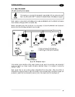
Страница 91: ...r Host Mode programming In Local Echo communication mode data is transmitted on the RS232 auxiliary interface independently from the Fieldbus interface selection When One Shot or Phase Mode operating...

Страница 92: ...xample a pulse from a photoelectric sensor when the object enters its reading zone Applications can be implemented to connect a device such as a hand held reader to the Auxiliary port of the last read...

Страница 93: ...y messages received by its Auxiliary interface onto the ID NET interface The Master passes all messages to the Host When One Shot or Phase Mode operating mode is used the reader can be activated by an...

Страница 94: ...nd a single message from the master reader to the Host computer It is not necessary to bring the External Trigger signal to all the readers In the Master Slave Synchronized layout the Master operating...

Страница 95: ...the QL300 Master and into the last QL in the network Slave Nodes CBL 1480 xx CAB PW EXT CBL 1480 xx Aux QL300 Master QL150 ID NET Aux CBL 1496 ID NET Terminator Host QL150 3 1 4 PS Power CBX500 CBL 1...

Страница 96: ...to Host An alternative layout to the CBXs can be made using QLs Figure 97 ID NET M S Synchronized Layout with QL500 TCP IP Ethernet Interface to Host CBX500 BM200 210 TCP IP Ethernet Interface Extern...

Страница 97: ...can be used in Local Echo communication mode to control any single reader visualize collected data or to configure it using the VisiSet utility The ID NET termination resistor switches must be set to...

Страница 98: ...rnet Interface to Host NOTE The auxiliary serial interface of the slave readers can be used in Local Echo communication mode to control any single reader visualize collected data or to configure it us...

Страница 99: ...9 pin connector using the VisiSet configuration program or Host Mode programming Figure 100 ID NET Fieldbus M S Synchronized Layout Figure 101 ID NET Fieldbus M S Multidata Terminal Fieldbus Interfac...

Страница 100: ...he messages received by the auxiliary interface onto the main interface All messages will be passed through this chain to the Master The Master reader is connected to the Host on the RS232 RS485 main...

Страница 101: ...ss for each reader Figure 103 Multiplexer Layout The auxiliary serial interface of the slave readers can be used in Local Echo communication mode to control any single reader visualize collected data...

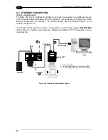
Страница 102: ...via VisiSet For further details see the Ethernet Folder in the VisiSet Help On Line In a Point to Point layout the reader is connected to a local host by using a CAB ETH M0x cable There is no need to...

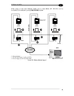
Страница 103: ...210 21X X1X can be connected to the network by using CAB ETH M0x cables Figure 105 Ethernet Network Layout CBX Matrix 210 HOST NETWORK Power CAB ETH M0x CAB MSxx 1 2 3 Ethernet Interface Auxiliary Se...

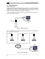
Страница 104: ...ough the Communication parameters via VisiSet For further details see the Communication Folder in the VisiSet Help On Line In a Point to Point layout the reader is connected to a local host through it...

Страница 105: ...10 85 3 35 135 5 31 Typ 0 38 15 70 2 76 192 7 55 1 Focus Distance 2 Pixels per inch Focus Distance 3 Measurement Conditions Test Chart provided with the reader Still code at the center of the FOV Code...

Страница 106: ...rection of movement is parallel to the elements of the code the maximum speed is greater Assuming X Code Resolution mm Texp Exposure Time s LS Line Speed mm s The essential condition to avoid blurring...

Страница 107: ...ure time Three different lighting levels can be set NOTE To avoid LED array overheating for Power Strobed settings the program automatically limits the range of allowed values for the Exposure Time pa...

Страница 108: ...ule See the Configuration Through Ethernet page in the VisiSet Help On Line or the Matrix Family Setup Procedure Using Programming Barcodes document on the Mini DVD 8 1 VISISET SYSTEM REQUIREMENTS To...

Страница 109: ...ally enters Run Mode 2 Run the VisiSet program 3 Press Connect on the VisiSet menu bar The PC will automatically connect to the Matrix 210 reader Upon connection Matrix 210 exits Run Mode and displays...

Страница 110: ...he Options item from the VisiSet menu see Figure 108 presents a window allowing you to configure the logging function Log VisiSet window properties Environment VisiSet communication channel Communicat...

Страница 111: ...SOFTWARE CONFIGURATION 101 8 Figure 111 Options Communication Figure 112 Options Communication Ethernet...

Страница 112: ...eractive Mode by pressing the interactive button 5 Save the new configuration to the reader permanent memory by pressing the Send button NOTE Especially for lengthy configurations in Interactive Mode...

Страница 113: ...arameter or Group a pop up menu appears allowing you to directly manage that particular parameter or group You can View the Selected Value for each parameter You can Restore the Default Value of each...

Страница 114: ...2 WebSentinel Enables the Ethernet WebSentinel Agent for communication with the Datalogic WebSentinel plant array monitor Ethernet For 21x x1x models Sets the parameters related to the on board Ethern...

Страница 115: ...aved configuration file ini 8 4 2 Send Configuration Options The device parameters are divided into two main classes Configuration and Environmental which are effected differently by the Send Configur...

Страница 116: ...Slave Address Network Baud Rate Acquisition Trigger String available only in Multidata configuration Reading Phase ON String available only in Multidata configuration Reading Phase OFF String availabl...

Страница 117: ...Gateway Address PROFIBUS Node Address DEVICENET Node Address ETHERNET IP IP Addressing Mode IP Address Subnet Mask Gateway Address PROFINET IO IP Addressing Mode IP Address Subnet Mask Gateway Address...

Страница 118: ...nd Environmental parameters to the new device To do this select Send Configuration with Options from the Device Menu and check the Environmental Parameters checkbox In order to return a device to its...

Страница 119: ...114 Calibration OK This tool provides a real time image display while Matrix 210 is reading It also gives immediate results on the performance of the installed Matrix 210 reader If Self Tuning is ena...

Страница 120: ...les show some of the typical conditions occurring during the installation Under exposure To correct this result it is recommended to change the following parameters in their order of appearance 1 incr...

Страница 121: ...ON 111 8 Over exposure To correct this result it is recommended to change the following parameters in their order of appearance 1 decrease the Gain 2 decrease the Exposure Time Figure 116 Example Over...

Страница 122: ...d of View To correct this result and have the code completely visible in F O V it is possible to follow one or both the procedures listed below reposition the reader use the Acquisition Trigger Delay...

Страница 123: ...a new group 8 4 5 Run Time Self Tuning RTST Run Time Self Tuning RTST increases Matrix s flexibility in the presence of uncontrolled variable conditions lighting code contrast etc by automatically adj...

Страница 124: ...eft and Right parameters allow to precisely define the image window to be processed visualized and saved In Matrix 210 the frame rate is dependent on the number of rows and columns in the defined wind...

Страница 125: ...ty The Direct Marking selection improves the decode rate for low quality Direct Part Mark codes and in general for Direct Part Mark codes with dot peening type module shapes Washed out and Axial Disto...

Страница 126: ...t mark codes A different filter can be applied to each Image Acquisition Setting The Erode Filter enlarges the image dark zones to increase readability Before No Read After Readable Erode The Dilate F...

Страница 127: ...17 8 The Open filter eliminates white areas defects in the dark zones of the image Before No Read After Readable Open The Contrast Stretching filter maximizes image contrast Before No Read After Reada...

Страница 128: ...distribution uniform Before No Read After Readable Histogram Equalization The Smoothing filter deletes small insignificant details in the center of the image Before No Read After Readable Smoothing Th...

Страница 129: ...able Deblurring The Black Enhancement filter produces a nonlinear increase in the black level for light images Before No Read After Readable Black Enhancement The White Enhancement filter produces a n...

Страница 130: ...ded Data Position and Orientation Decode Time and Code Quality Assessment Metrics Figure 118 Capture and Decoding Functions 8 6 STATISTICS Statistics on the reading performance can be viewed by enabli...

Страница 131: ...re A 1 periodically for continued correct operation of the reader Dust dirt etc on the window may alter the reading performance Repeat the operation frequently in particularly dirty environments Use s...

Страница 132: ...Order Number can be obtained by applying the respective command in the Tools menu TROUBLESHOOTING GUIDE Problem Suggestion Power ON the POWER LED is not lit Is power connected If using a power adapter...

Страница 133: ...In the Data Collection folder check the settings for the CODE COLLECTION DATA FORMAT and STATISTICS parameter groups Image not clear Verify the Focus procedure Image focused but not decoded Verify th...

Страница 134: ...ain my reader Serial Number The reader Serial Number consists of 9 characters one letter 2 numbers another letter followed by 5 numbers The reader Serial Number is printed on a label that is affixed o...

Страница 135: ...ILoad 0 mA Max 30 Vdc 30 Vdc VOut ILoad 10 mA Max 1 8 Vdc 1 8 Vdc PD VOut ILoad Max 170 mW 170 mW OPTICAL FEATURES Image Sensor CMOS sensor with Global Shutter Image Format WVGA 752x480 Frame Rate up...

Страница 136: ...ost PLANET POSTNET POSTNET BB Intelligent Mail Swedish Post Operating Mode ONE SHOT CONTINUOUS PHASE MODE Configuration Methods X PRESS Human Machine Interface Windows based SW VisiSet via serial Ethe...

Страница 137: ...es its own unique format BIOS Basic Input Output System A collection of ROM based code with a standard API used to interface with standard PC hardware Bit Binary digit One bit is the basic unit of bin...

Страница 138: ...ost A computer that serves other terminals in a network providing services such as network control database access special programs supervisory programs or programming languages Image Processing Any f...

Страница 139: ...tterns which do not follow the same rules as the other elements within the symbol Multidrop A communication protocol for connecting two or more readers in a network with a concentrator or controller a...

Страница 140: ...Capture and Decoding 120 Inputs 53 73 Installing VisiSet 98 L Layouts 79 M M12 D 4 Pin Connector Ethernet 61 Main Serial Interface 42 61 Maintenance 121 Mechanical Dimensions 37 Model Description 31 M...

Страница 141: ...C EMC Directive ______________________________________________ This Declaration is based upon compliance of the products to the following standards EN 55022 CLASS A ITE DECEMBER 2010 INFORMATION TECHN...

Страница 142: ...www datalogic com...

Отзывы: