MATRIX 210™ REFERENCE MANUAL
6
1
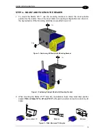
3. Refer to the Reading Features table in chp. 7 to determine the distance your reader
should be positioned at.
NOTE
Rapid Configuration of the Matrix 210™ reader can be made
either
through
the X-
PRESS™ interface (steps 3-4) which requires no PC connection,
or
by using the VisiSet™ Setup Wizard (steps 5-6). Select the procedure
according to your needs.
STEP 3
– AIM THE READER
Matrix 210™ provides a built-in aiming system to aid reader positioning. The aiming system
is accessed through the X-
PRESS™ Interface.
1. Power the reader on. During the reader startup (reset or restart phase), all the LEDs blink
for one second. On the connector side of the reader near the cable, the “POWER ON”
LED (blue) indicates the reader is correctly powered.
2. Enter the Aim/Locate function by pressing and holding the X-
PRESS™ push button until
the Aim LED is on.
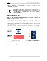
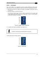
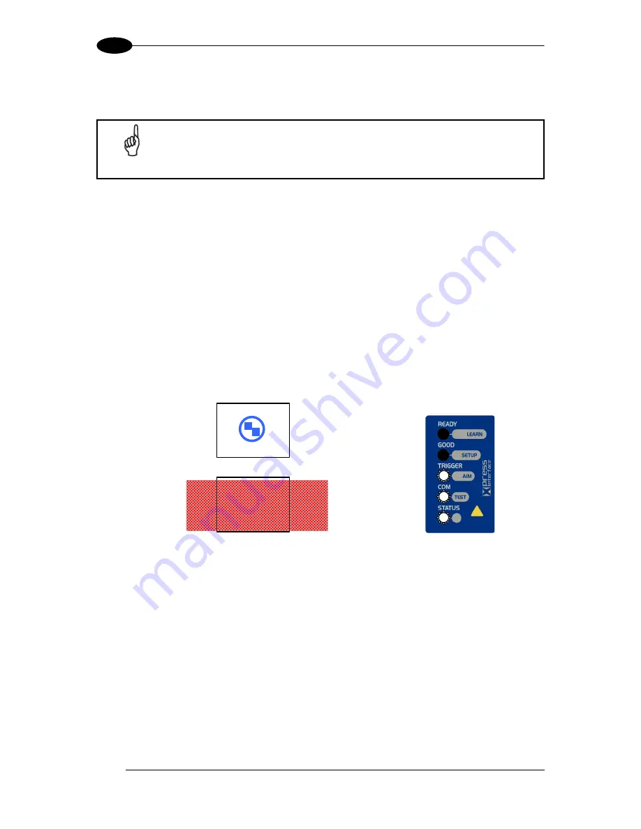
3. Release the button to enter the Aim function. The aiming system turns on see Figure 6.
4. Place the application specific code in front of the reader at the reading distance indicated
for your model in the Reading Features table, centering it in the aiming system indicator.
FOV
default value for:
UHD models
default value for:
NEAR, MEDIUM,
FAR models
FOV
Figure 6
– Aiming Function Using The Blue Ring or
Internal Lighting System *
green
green
yellow
yellow
red
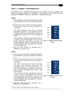
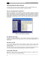
Figure 7
– X-PRESS™ Interface: Aim Function
* the default value of the Aiming System Status parameter can be changed in VisiSet™.
5. Exit the Aim function by pressing the X-
PRESS™ push button once. The aiming system
turns off.
Содержание Matrix 210
Страница 1: ...MATRIX 210 Reference Manual...
Страница 59: ...CBX ELECTRICAL CONNECTIONS 49 4 Figure 45 ID NET Network Connections with isolated power blocks...
Страница 60: ...MATRIX 210 REFERENCE MANUAL 50 4 Figure 46 ID NET Network Connections with Common Power Branch Network...
Страница 61: ...CBX ELECTRICAL CONNECTIONS 51 4 Figure 47 ID NET Network Connections with Common Power Star Network...
Страница 78: ...MATRIX 210 REFERENCE MANUAL 68 5 Figure 71 ID NET Network Connections with isolated power blocks...
Страница 79: ...25 PIN CABLE ELECTRICAL CONNECTIONS 69 5 Figure 72 ID NET Network Connections with Common Power Branch Network...
Страница 80: ...MATRIX 210 REFERENCE MANUAL 70 5 Figure 73 ID NET Network Connections with Common Power Star Network...
Страница 111: ...SOFTWARE CONFIGURATION 101 8 Figure 111 Options Communication Figure 112 Options Communication Ethernet...
Страница 142: ...www datalogic com...

