MATRIX 210™ REFERENCE MANUAL
86
6
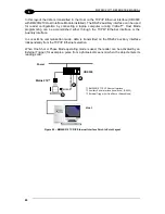
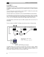
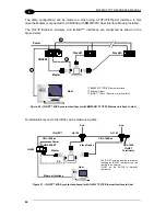
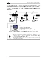
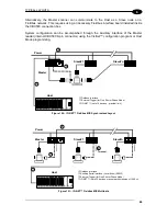
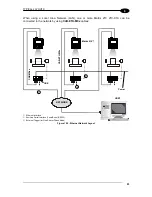
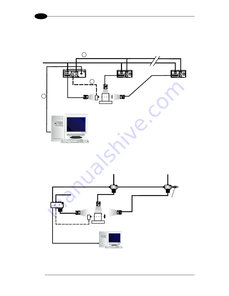
The same configuration can be made to a Host using a TCP/IP Ethernet interface. In this
case the Master is connected to a CBX500 with BM200/210 Host Interface Module installed.
The TCP/IP Ethernet, auxiliary, and ID-
NET™ interfaces are connected as shown in the
figure below.
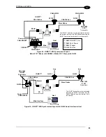
Figure 96
– ID-NET™ M/S Synchronized Layout with BM200/210 TCP/IP Ethernet Interface to Host
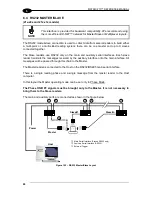
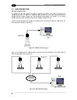
An alternative layout to the CBXs can be made using QLs:
Figure 97 - ID-
NET™ M/S Synchronized Layout with QL500 TCP/IP Ethernet Interface to Host
CBX500
BM200/210 TCP/IP Ethernet Interface
External Trigger
ID-
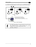
NET™ (up to 16 devices - practical limit)
Host
1
3
2
Master
Slave#1
Slave#n
Power
Host
QL150
PS
Power
Ethernet Interface
CBL-1490
ID-NET
Terminator
The ID-NET network must be terminated
inserting an ID-NET terminator into the
last QL in the network.
ID-NET on the QL500 is internally
terminated.
Slave Nodes
CBL-1480-xx
CAB-PW-EXT
CBL-1480-xx
Aux
QL500
Master
QL150
ID-
NET™
Aux
Содержание Matrix 210
Страница 1: ...MATRIX 210 Reference Manual...
Страница 59: ...CBX ELECTRICAL CONNECTIONS 49 4 Figure 45 ID NET Network Connections with isolated power blocks...
Страница 60: ...MATRIX 210 REFERENCE MANUAL 50 4 Figure 46 ID NET Network Connections with Common Power Branch Network...
Страница 61: ...CBX ELECTRICAL CONNECTIONS 51 4 Figure 47 ID NET Network Connections with Common Power Star Network...
Страница 78: ...MATRIX 210 REFERENCE MANUAL 68 5 Figure 71 ID NET Network Connections with isolated power blocks...
Страница 79: ...25 PIN CABLE ELECTRICAL CONNECTIONS 69 5 Figure 72 ID NET Network Connections with Common Power Branch Network...
Страница 80: ...MATRIX 210 REFERENCE MANUAL 70 5 Figure 73 ID NET Network Connections with Common Power Star Network...
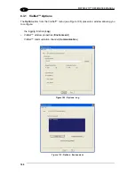
Страница 111: ...SOFTWARE CONFIGURATION 101 8 Figure 111 Options Communication Figure 112 Options Communication Ethernet...
Страница 142: ...www datalogic com...


