MATRIX 210™ REFERENCE MANUAL
30
2
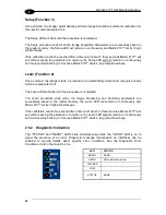
Setup (Function 3)
Once entered, the imager automatically performs Image Acquisition parameter calibration for
the specific code presented to it.
The Setup LED will blink until the procedure is completed.
The Setup procedure ends when the Image Acquisition parameters are successfully saved in
the reader memory, the Setup LED will remain on continuously and Matrix 210™ emits 3 high
pitched beeps.
If the calibration cannot be reached after a timeout of about
5 (five) seconds Matrix 210™ will
exit without saving the parameters to memory, the Setup LED will not remain on continuously
but it will just stop blinking. In this case Matrix 210™ emits a long low pitched beep.
Learn (Function 4)
Once entered, the imager starts a procedure to automatically detect and recognize codes
which are presented to it.
The Learn LED will blink until the procedure is completed.
The Learn procedure ends when the Image Processing and Decoding parameters are
successfully saved in the reader memory, the Learn LED will remain on continuously and
Matrix 210™ emits 3 high pitched beeps.
If the calibration cannot be reached after a timeout of about 3 (three) minutes, Matrix 210™ will
exit without saving the parameters to memory, the Learn LED will not remain on continuously
but it will just stop blinking. In this case Matrix 210™ emits a long low pitched beep.
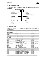
2.5.2 Diagnostic Indication
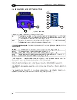
The "STATUS" and "READY" LEDs blink simultaneously while the "GOOD" LED is on to
signal the presence of an error. Diagnostic message transmission on interfaces can be
enabled to provide details about specific error conditions. See the Diagnostic Error
Conditions chart in the Help On Line.
LED
STATUS
READY
BLINK
GOOD
ON to indicate an error
TRIGGER
COM
STATUS
BLINK
Содержание Matrix 210
Страница 1: ...MATRIX 210 Reference Manual...
Страница 59: ...CBX ELECTRICAL CONNECTIONS 49 4 Figure 45 ID NET Network Connections with isolated power blocks...
Страница 60: ...MATRIX 210 REFERENCE MANUAL 50 4 Figure 46 ID NET Network Connections with Common Power Branch Network...
Страница 61: ...CBX ELECTRICAL CONNECTIONS 51 4 Figure 47 ID NET Network Connections with Common Power Star Network...
Страница 78: ...MATRIX 210 REFERENCE MANUAL 68 5 Figure 71 ID NET Network Connections with isolated power blocks...
Страница 79: ...25 PIN CABLE ELECTRICAL CONNECTIONS 69 5 Figure 72 ID NET Network Connections with Common Power Branch Network...
Страница 80: ...MATRIX 210 REFERENCE MANUAL 70 5 Figure 73 ID NET Network Connections with Common Power Star Network...
Страница 111: ...SOFTWARE CONFIGURATION 101 8 Figure 111 Options Communication Figure 112 Options Communication Ethernet...
Страница 142: ...www datalogic com...

