INTRODUCTION
21
2
7.
Configure the other device parameters via VisiSet™ [Operating Mode, Calibration, Data
Collection parameters, etc.].
8. The Slave device is now Configured. Physically connect it to the Master/Slave network. If
using the CBX connection box equipped with a BM100 Backup module, you can perform
Device Backup at the Slave (see par. 2.4 for details).
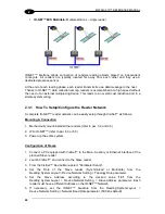
Repeat these steps for each Slave reader in the ID-
NET™ network.
Configuration of Master
1.
Connect a PC equipped with VisiSet™ to the Main, Auxiliary or Ethernet interface of the
planned Master reader.
2.
Launch VisiSet™ and connect to the Master reader.
3.
From the VisiSet™ Device Menu select "Parameter Setup".
4. Set the Role of the Master reader (Synchronized or Multidata) from the
Reading System Layout > Device Network Setting > Topology Role parameter.
5. Enable the planned Slave device N
from the Reading System Layout >
Expected Slave Device #N > Status parameter and, if desired, set the related
identification string from the Expected Slave Device #N > Device Description parameter.
Repeat this step for all planned Slave devices.
6. If necessary, set the ID-
NET™ baudrate from the Reading System Layout >
Device Network Setting > Network Baud Rate parameter, (500 kbs default).
7.
Configure the other device parameters via VisiSet™ [Operating Mode, Calibration, Data
Collection parameters, etc.].
8. The Master device is now Configured. Physically connect it to the Master/Slave network.
If using the CBX connection box equipped with a BM100 Backup module, perform a
Network Backup at the Master (see par. 2.4 for details).
9.
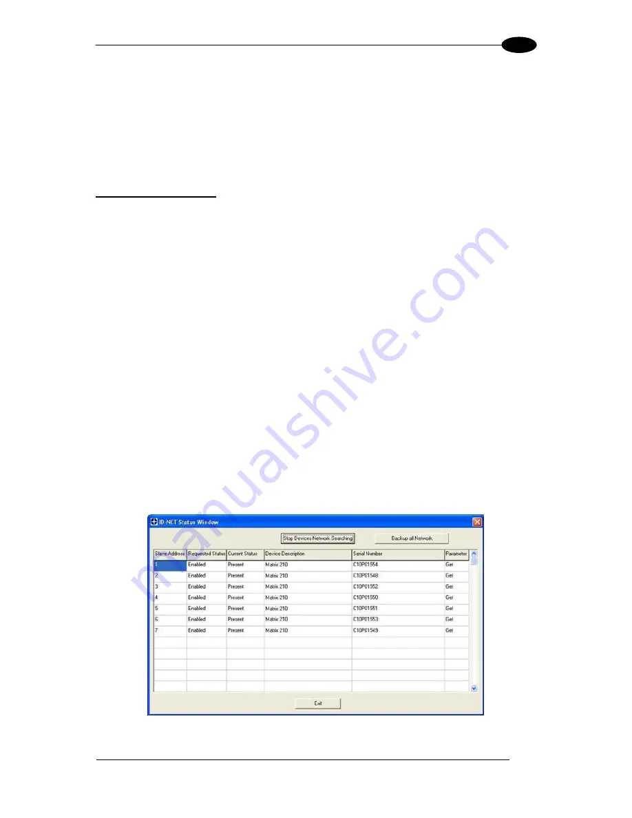
From the VisiSet™ Device Menu select "ID-NET™ Status Window" and click on the
"Look For Devices On Network" button to check the status of the expected Slave devices
within the ID-
NET™ network.
The reader network is ready.
Содержание Matrix 210
Страница 1: ...MATRIX 210 Reference Manual...
Страница 59: ...CBX ELECTRICAL CONNECTIONS 49 4 Figure 45 ID NET Network Connections with isolated power blocks...
Страница 60: ...MATRIX 210 REFERENCE MANUAL 50 4 Figure 46 ID NET Network Connections with Common Power Branch Network...
Страница 61: ...CBX ELECTRICAL CONNECTIONS 51 4 Figure 47 ID NET Network Connections with Common Power Star Network...
Страница 78: ...MATRIX 210 REFERENCE MANUAL 68 5 Figure 71 ID NET Network Connections with isolated power blocks...
Страница 79: ...25 PIN CABLE ELECTRICAL CONNECTIONS 69 5 Figure 72 ID NET Network Connections with Common Power Branch Network...
Страница 80: ...MATRIX 210 REFERENCE MANUAL 70 5 Figure 73 ID NET Network Connections with Common Power Star Network...
Страница 111: ...SOFTWARE CONFIGURATION 101 8 Figure 111 Options Communication Figure 112 Options Communication Ethernet...
Страница 142: ...www datalogic com...

