INTRODUCTION
29
2
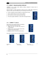
Release button
to enter Setup Mode
Release button
to enter Learn Mode
(cycle)
Release button
to Exit
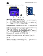
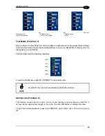
Test Mode (Function 1)
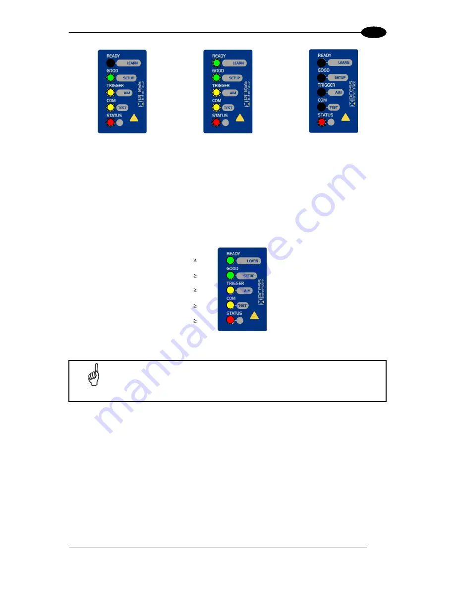
Once entered, the Bar Graph on the five LEDs is activated and if the imager starts reading
codes the Bar-Graph shows the Good Read Rate. In case of a NO READ condition, only the
Status
LED is on and blinks.
The Bar Graph has the following meaning:
95%
75%
60%
40%
20%
To exit the Test Mode, press the X-
PRESS™ push button once.
NOTE
By default, the Test exits automatically after three minutes.
Aim/Locate (Function 2)
This function causes the blue ring to turn on. Since the blue ring is centered on the FOV it
can be used to position the imager on the code. The Aim LED blinks to indicate this state.
To exit the Aim/Locate Mode, press the X-PRE
SS™ push button once. The blue ring turns
off.
Содержание Matrix 210
Страница 1: ...MATRIX 210 Reference Manual...
Страница 59: ...CBX ELECTRICAL CONNECTIONS 49 4 Figure 45 ID NET Network Connections with isolated power blocks...
Страница 60: ...MATRIX 210 REFERENCE MANUAL 50 4 Figure 46 ID NET Network Connections with Common Power Branch Network...
Страница 61: ...CBX ELECTRICAL CONNECTIONS 51 4 Figure 47 ID NET Network Connections with Common Power Star Network...
Страница 78: ...MATRIX 210 REFERENCE MANUAL 68 5 Figure 71 ID NET Network Connections with isolated power blocks...
Страница 79: ...25 PIN CABLE ELECTRICAL CONNECTIONS 69 5 Figure 72 ID NET Network Connections with Common Power Branch Network...
Страница 80: ...MATRIX 210 REFERENCE MANUAL 70 5 Figure 73 ID NET Network Connections with Common Power Star Network...
Страница 111: ...SOFTWARE CONFIGURATION 101 8 Figure 111 Options Communication Figure 112 Options Communication Ethernet...
Страница 142: ...www datalogic com...

