background image

DFX-7

 Ultrasonic Flaw Detector 

83 

7.6 Understanding the features of the Gate 

Important:

  It is recommended to spend some time in this section.  The sections that 

follow are procedures for using the features associated with the Gates, in some way.  
There are 3 gates in the 

DFX-7

, and as a result, operating and setting them up can 

become somewhat convoluted, to say the least.  However, a thorough understanding 
of the functionality presented in this section, will reveal how easy they actually are to 
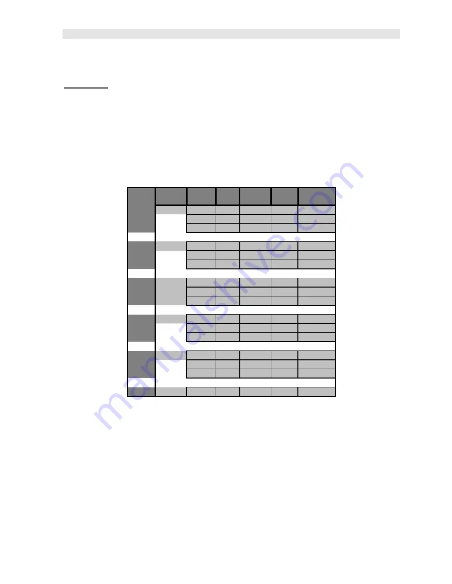
operate overall.  The following diagrams illustrate the features of all 3 gates, 
according to the measurement mode selected: 

Note:

  This is a general overview and should be referred to in conjunction with the 

detailed feature sections that follow. 
 

Modes # Gates Gate # Start HoldOff Width Threshold

PE

1,2,or 3

1

2

3

PECT

1,2,or 3

1

2

3

PETP

1,2,or 3

1

2

3

EE

2

1

2

3

EEV

3

1

2

3

CT

None

None

None

None

None

None


Diag. 1 Gate Features vs Modes 

 
In 

diagram 1

, the gates have been associated with the measurement modes, along 

with the features available to every gate.  For example, echo-echo mode (EE) has 2 
gates available, while echo-echo verify (EEV) has 3.  These gates have been 
designed to work in order, from 1 to 3, and cannot be used any other way.  
Therefore, the user must be using gate 2 before they can activate and use gate 3.  

Note:


Gate 1 is on at all times, as a gate must be activated to get a measurement.


Each gate has a given set of features to fine adjust the settings of the gate.  Let’s 
have a look at the feature set: 

Start (Gate1):

  This feature is only available to gate 1, and determines the start value 

of the left side of the gate.  For example, if there’s a great deal of noise from the initial 

Содержание DFX-7

Страница 1: ...Industrial LP USA Tel 1 281 516 9292 888 275 5772 eFax 1 866 234 0451 Web https www abqindustrial net E mail info abqindustrial net Distributed by ABQ Industrial LP USA Tel 1 281 516 9292 888 275 577...

Страница 2: ...ETRY MODE 50 CHAPTER SEVEN AWS WELD INSPECTION 55 CHAPTER EIGHT DISTANCE AMPLITUDE CORRECTION DAC 60 CHAPTER NINE TIME CORRECTED GAIN TCG 66 CHAPTER TEN ADDITIONAL FEATURES OF THE DFX 7 71 CHAPTER ELE...

Страница 3: ...ith a number of comprehensive toolkits to provide the user the arsenal necessary to address a number of common field applications In and effort to avoid complexity issues and differential between gaug...

Страница 4: ...7 use the UP DOWN arrow keys to select flaw detector followed by pressing the OK key start the DFX 7 in flaw mode If this is the first time the gauge has been used a general startup configuration will...

Страница 5: ...and multiple submenu items as illustrated below Refer to Chapter Three for additional definitions and information on the keypad and menu items Start PRB CAL DISP TUNE GT1 GT2 TRIG AWS TYPE MAT VIEW F...

Страница 6: ...reviously been used the basic default settings can be reloaded at any time as outlined below Load Default Setup The following section assumes the gauge is powered up the flaw detector option selected...

Страница 7: ...P and DOWN arrow keys to scroll through the sub menu items until DEFAULT SETUP is highlighted 3 Press the ENTER key to display the confirmation screen 4 Press the OK key to load the default setup and...

Страница 8: ...enu tab groups These tab groups then contain sub menu items or functions The sub menu items have been organized in the tab groups according to how closely they are related to the individual tab group...

Страница 9: ...familiar with activating and moving amongst the tab groups let s have a look at how to move around in the sub menu items as follows 2 Use the UP and DOWN arrow keys to scroll through the sub menu ite...

Страница 10: ...00 ohms Refer to page 90 for further info PULSER VOLT Adjustable pulser voltage 100 150 and 200 volt Refer to page 87 for a further explanation 3 3 CAL Menu MAT Select the material velocity from a cha...

Страница 11: ...r schemes to select from There are two schemes for each main color option Refer to page 77 for further info DIM Allows the user to conserve battery life by diming the display after idle for a specific...

Страница 12: ...waveform while ignoring others In order to detect on a waveform echo and display the amplitude as a percentage of full screen height the echo must be inside the boundaries of the gate settings The GA...

Страница 13: ...ng outlined above Refer to page 30 for further info POLARITY The gates can be set to detect on either the positive or negative polarity or stroke of the half or full wave cycle It should be noted that...

Страница 14: ...int of the probe to the front of the wedge can shoe case Refer to page 55 for further info 3 10 TCG Menu TCG This feature toggles the TCG feature on off The Time Corrected Gain TCG feature displays re...

Страница 15: ...dent gate The list of trigger options will change according to which CURVE option has been selected Refer to page 60 for further info DPOLARITY Used to select the polarity of the DAC curves generated...

Страница 16: ...xist in memory from a list of grids Refer to page 116 for further info CLOSE Provides the user the ability to close a currently opened grid or sequential log file Refer to page 118 for further info DE...

Страница 17: ...DFX 7 DakView software for a complete electronic manual ABOUT Provides the user with Dakota Ultrasonics contact information and the DFX 7 software version Refer to the Dakota Ultrasonics web site for...

Страница 18: ...and edit boxes display and save measurements waveforms to grid or sequential file locations 3 23 MULTI MODE Key The MULTI MODE key provides the user with a set of flaw mode options Normal Peak or Free...

Страница 19: ...f the sound path signal When all the vertical bars are fully illuminated the repeatability of the sound path is stable B Battery Icon Indicates the amount of battery life the DFX 7 has remaining C Hei...

Страница 20: ...been previous stored in memory When MEM is displayed all measurement functions are disabled until the user advances to an empty storage location or the current measurement is cleared by pressing the C...

Страница 21: ...o toggle the value or status Note This is a coarse adjustment It s the fastest and easiest way to increment decrement or toggle the status however it does so in coarse steps Set Detect 1 Press the UP...

Страница 22: ...7 s top end cap The transducer connectors are of type LEMO 00 A single element transducer must be plugged into the inside LEMO jack as illustrated above Note There is no polarity associated with conne...

Страница 23: ...serial cable Note This connector is also used to upgrade the DFX 7 with the latest version of firmware USB Serial to USB Converter Cable A converter cable can be attached to the 9 pin serial cable in...

Страница 24: ...sitive or negative from the reflector or return echo The user can select the polarity or phase displayed This is typically determined by first using RF view to select the most optimal polarity phase t...

Страница 25: ...e had a 50 widescreen television set The left side of the television screen is considered the Delay for all view options The right side of the television screen is the Range Delay By adjusting the lef...

Страница 26: ...keys to scroll the highlighted value 3 Alternatively press the ENTER key to display the Digits Edit Box 4 Press the UP and DOWN arrow keys to scroll the highlighted value 5 Press the LEFT and RIGHT a...

Страница 27: ...imes to move left until the RANGE cell is highlighted 2 Press the UP DOWN LEFT and RIGHT arrow keys to scroll the highlighted value 3 Alternatively press the ENTER key to display the Digits Edit Box 4...

Страница 28: ...ect Not enough gain may result in intermittent detection It may also result in lack of detection on internal flaws pits or porosity The gain can easily be compared to the volume control of a home ster...

Страница 29: ...NTER key to display the Digits Edit Box 4 Press the UP and DOWN arrow keys to scroll the highlighted value 5 Press the LEFT and RIGHT arrow keys to scroll the digit locations 6 Repeat steps 4 5 until...

Страница 30: ...e TUNE menu is highlighted and displaying the submenu items 2 Use the UP and DOWN arrow keys to scroll through the sub menu items until GAIN is highlighted 3 Press the LEFT and RIGHT arrow keys to scr...

Страница 31: ...or example a test block with a target size and depth is optimized on the A Scan display with a signal amplitude at 70 full screen height The inspector wants to know of any defects during the inspectio...

Страница 32: ...s to tab right and the ESC key multiple times to tab left until the GT1 menu is highlighted and displaying the submenu items 2 Use the UP and DOWN arrow keys to scroll through the sub menu items until...

Страница 33: ...5 Repeat steps 3 4 until the start position is correctly displayed 6 Press the OK key to set the GATE1 start position and return to the menu screen or ESC to cancel entering the GATE1 start position N...

Страница 34: ...Press the UP and DOWN arrow keys to scroll the highlighted value 4 Press the LEFT and RIGHT arrow keys to scroll the digit locations 5 Repeat steps 3 4 until the threshold level is correctly displayed...

Страница 35: ...Dakota Ultrasonics 34 Note Sets where the detection will occur on the negative or positive going echoes...

Страница 36: ...built into a single gauge a flaw detector and a thickness gauge Therefore while the flaw detector option can be calibrated for straight beam contact and angle beam style transducers the thickness gau...

Страница 37: ...ng Default Setup 1 Press the MENU key once to activate the menu items tab Press the MENU key multiple times to tab right and the ESC key multiple times to tab left until the SEUTP menu is highlighted...

Страница 38: ...to the GT1 menu Note Our range calibration range for this example is 4 inches Therefore setting a range of 5 inches will enable the user to view the entire range on the display Enabling and Setting Up...

Страница 39: ...ghted 3 Press the LEFT and RIGHT arrow keys to toggle the gate ON Setting the Detect 1 Use the UP and DOWN arrow keys to scroll through the sub menu items until DETECT is highlighted 2 Press the LEFT...

Страница 40: ...WIDTH value is displayed Note In our example a value greater than 1 inch should be selected 6 Press the OK key to set the value and return to the GT1 menu Threshold Level 1 Use the UP and DOWN arrow k...

Страница 41: ...on 5 2 Straight Beam Calibration Now that the DFX 7 is setup with a valid range and a gate enabled we re ready to perform a two point calibration using a single element contact style transducer as fol...

Страница 42: ...he MEAS key multiple times to move right and the ESC key multiple times to move left until the GATE1 cell is highlighted 2 Press the LEFT and RIGHT arrow keys to move the gate over the waveform to be...

Страница 43: ...eps 4 5 until the known thickness value is correctly displayed 7 Press the OK key to calculate the velocity and return to the menu screen or ESC to cancel the one point calibration Apply a drop of cou...

Страница 44: ...the gate over the waveform to be measured as demonstrated in the screen shot above Note In order to trigger on a signal the waveform must be inside the boundaries of the gate Calibrating the Second Po...

Страница 45: ...point calibration Note A velocity and zero value will be calculated and displayed in the fields a shown above 8 Finally press the MEAS key to return to the measurement screen In order to trigger on an...

Страница 46: ...multiple times to move right and the ESC key multiple times to move left until the GATE1 cell is highlighted 2 Press the LEFT and RIGHT arrow keys to move the gate start to a position less than 1 inch...

Страница 47: ...ement straight beam contact transducer With the exception of a handful of additional comments calibration using an angle beam transducer is virtually identical in the scope of the overall step by step...

Страница 48: ...ducer on the calibration standard The user should select a screen height and gain level that will enable the entire waveform to be visible on the display Peaking Up the Signal Amplitude During an angl...

Страница 49: ...hted and displaying the submenu items 2 Press the LEFT and RIGHT arrow keys to toggle TRIG mode ON 3 Press the MENU key once to activate the menu items tab Press the MENU key multiple times to tab rig...

Страница 50: ...Flaw Detector 49 7 Press the ENTER key to select the material type and initiate the overwrite confirmation screen 8 Press the OK key to confirm the material selection or ESC key to cancel changing th...

Страница 51: ...e weld at a given angle Therefore in order to determine the location of a defect given a specific angle the trigonometry mode is used This section will cover the steps to setup and utilize trigonometr...

Страница 52: ...an a flat surface will using a transducer with a given angle The user should consider the angle used on curved surfaces with respect to the material thickness in order to be sure a reflection will occ...

Страница 53: ...b menu items until TRIG is highlighted 3 Press the LEFT and RIGHT arrow keys to toggle the TRIG feature ON The menu items should now become active and adjustable as illustrated above Enter Material Th...

Страница 54: ...Digits Edit Box 3 Press the UP and DOWN arrow keys to scroll the highlighted value 4 Press the LEFT and RIGHT arrow keys to scroll the digit locations 5 Repeat steps 3 4 until the angle is correctly d...

Страница 55: ...d by pressing the LEFT and RIGHT arrow keys to scroll the value When the correct CSC OD is displayed proceed to the next setting 2 Alternatively press the ENTER key to display the Digits Edit Box 3 Pr...

Страница 56: ...Level IL C Attenuation Factor AF or 2 SP 1 SP sound path in inches 2dB loss per inch of material thickness D Indication Rating IR Note all values are in dB Calibration Standards Calibration In order t...

Страница 57: ...highlighted and displaying the submenu items 2 Use the UP and DOWN arrow keys to scroll through the sub menu items until AWS is highlighted 3 Press the LEFT and RIGHT arrow keys to toggle the AWS feat...

Страница 58: ...full screen height Setting the Reference Gain 1 Press the UP and DOWN arrow keys until SET REF HEIGHT is highlighted followed by pressing the LEFT and RIGHT arrow keys to toggle the feature ON 2 Press...

Страница 59: ...l the AWS BOX cell is highlighted 2 Press the LEFT and RIGHT arrow keys to position the cursor box over the waveform 3 Press the ENTER key to set the REFGN reference gain Note This process can be repe...

Страница 60: ...DFX 7 Ultrasonic Flaw Detector 59 Note The AWS screen can be toggle on by pressing the OK key while in the main measurement screen Equally the Hot Menus can be toggled by pressing the MEAS at any time...

Страница 61: ...set to TRIGGER on any of the curve options displayed Therefore if the 6 12dB curve option has been selected the user can toggle the TRIGGER options GATE DAC 6dB or 12dB Note Based on the screen resol...

Страница 62: ...rsor over a waveform to use as a point in generating the DAC curve the DAC BOX hot menu item in the main measurement screen must be highlighted 8 3 Creating a DAC Curve This section provides a step by...

Страница 63: ...arrow keys to toggle and select dB FSH or DAC Selecting the Curve s 1 Press the UP and DOWN arrow keys until CURVE is highlighted followed by pressing the LEFT and RIGHT arrow keys to toggle and selec...

Страница 64: ...C Drawing the DAC 1 With all the parameters set in the previous section press the MEAS key once to return to the main measurement screen Note The user should now see a highlighted cursor displayed in...

Страница 65: ...hs in the overall range to be tested 4 Press the LEFT and RIGHT arrow keys to move the cursor over the waveform to be used as the first point in the DAC curve and press the ENTER key to set the first...

Страница 66: ...Flaw Detector 65 7 Press the UP and DOWN arrow keys until DRAW is highlighted followed by pressing the LEFT and RIGHT arrow keys until OFF is displayed The DAC curves are now set and ready to be used...

Страница 67: ...better solution for any materials that attenuate more than 18dB over the inspection range and should be considered 9 2 Additional Comments Prior to proceeding onto the next section to create a DAC cur...

Страница 68: ...ys to toggle the TCG feature ON The menu items should now become active and adjustable as illustrated above Enter Screen Height 7 Press the UP and DOWN arrow keys until SCRN HEIGHT is highlighted foll...

Страница 69: ...u items until DRAW is highlighted 5 Press the LEFT and RIGHT arrow keys to toggle the DRAW feature ON 6 Proceed to the next section Drawing the TCG curve Drawing the TCG 1 With all the parameters set...

Страница 70: ...4 Press the LEFT and RIGHT arrow keys to move the cursor over the waveform to be used as the first point in the TCG curve and press the ENTER key to set the first point Illustrated in ex 1 above 5 Rep...

Страница 71: ...rrow keys until OFF is displayed The TCG curve is now set 8 Optionally the TCG curve can be displayed by pressing the UP and DOWN arrow keys until CURVE is highlighted followed by pressing the LEFT an...

Страница 72: ...elocity are outlined below Adjusting Velocity 1 Press the MENU key once to activate the menu items tab Press the MENU key multiple times to tab right and the ESC key multiple times to tab left until t...

Страница 73: ...ement screen 10 2 Zero The DFX 7 has a feature to manually adjust the electronic zero This feature used in conjunction with manually adjusting the velocity are the primary features necessary to perfor...

Страница 74: ...ations 7 Repeat steps 5 6 until the zero value is correctly displayed 8 Press the OK key to set the zero and return to the menu screen or ESC to cancel entering the zero 9 Finally press the MEAS key t...

Страница 75: ...aying the submenu items 2 Use the UP and DOWN arrow keys to scroll through the sub menu items until MAT is highlighted 3 Press the ENTER key to display the list of material types 4 Press the UP and DO...

Страница 76: ...w on the display Once the echo is in the viewable area the user can then make small adjustments to the delay and range accordingly The procedure to use the AUTO FIND feature is outlined below Using Au...

Страница 77: ...ze battery life It has an arbitrary scale with a values from 1 20 with 20 representing the brightest setting The procedures for adjusting the brightness are outlined below Adjusting Brightness 1 Press...

Страница 78: ...croll the digit locations 7 Repeat steps 5 6 until the brightness number is correctly displayed 8 Press the OK key to set the brightness and return to the menu screen or ESC to cancel entering the bri...

Страница 79: ...g the submenu items 2 Use the UP and DOWN arrow keys to scroll through the sub menu items until VIEW is highlighted 3 Press the ENTER key to display a list of the color scheme options 4 Press the UP a...

Страница 80: ...feature does not override the preset 5 min idle power off feature in any way However if the gauge is turned on set for a DIM of 120sec and then left idle for 5 minutes the DFX 7 will dim in 2 minutes...

Страница 81: ...atures for user preference when viewing the waveform These features only serve as cosmetic items and do not change the functionality of the DFX 7 in any way RECT Wave The rectified wave feature is onl...

Страница 82: ...multiple times to tab right and the ESC key multiple times to tab left until the DISP menu is highlighted and displaying the submenu items 2 Use the UP and DOWN arrow keys to scroll through the sub m...

Страница 83: ...e important thing to note is the polarity view is entirely different than the polarity selection of a gate If a polarity view of RECT is selected only the positive portion of the waveform will be show...

Страница 84: ...the center line The baseline is found at position A and considered zero dB If RECT was selected as the view only the positive portion of the waveform would be displayed Equally if the gate polarity w...

Страница 85: ...l the DISP DAC GT1 or GT2 menu is highlighted and displaying the submenu items 2 Use the UP and DOWN arrow keys to scroll through the sub menu items until VIEW DPOLARITY POLARITY1 or POLARITY2 is high...

Страница 86: ...t half cycle left edge rises and breaks the threshold Peak The detection occurs at the highest peak in the gate The procedure to select the DETECT MODE is outlined below Selecting the Detect 5 Press t...

Страница 87: ...desirable for high resolution and general applications to decrease the overall noise When additional energy is needed more penetration the THIN and WIDE options may be necessary The standard setting i...

Страница 88: ...offer greater penetration for difficult material types or increased resolution on noisy materials The procedure to change the pulser voltage is outlined below Changing the Pulser Voltage 1 Press the...

Страница 89: ...ovide the user the option to conserve on battery life The procedure to toggle this option is outlined below Selecting the Refresh 1 Press the MENU key once to activate the menu items tab Press the MEN...

Страница 90: ...as a response rate of less than 60Hz The PRF setting will automatically be overridden according to the range set by the user Long range settings will slow the PRF down automatically Slower PRF setting...

Страница 91: ...her impedance and distort The reverse is true for higher frequency transducers Nevertheless trial and error with this feature will enable you to find the optimal signal response and setting for your t...

Страница 92: ...s responsive to all signals within the given frequency range However narrow band filters eliminate signals outside of the target filter frequency and focus on the output of the transducer at the speci...

Страница 93: ...n an effort to peak up on a signal and locate the maximum amplitude The following procure outlines the steps to activate and use the PEAK hold feature Activating Peak 1 Press the MULTI MODE key locate...

Страница 94: ...ions 2 Use the UP and DOWN arrow keys NORMAL is highlighted 3 Press the ENTER key to set the mode and automatically return to the measurement screen 10 19 Freeze Waveform The DFX 7 also includes a FRE...

Страница 95: ...OWN arrow keys FREEZE is highlighted 3 Press the ENTER key to set the mode and automatically return to the measurement screen Disabling Freeze Note In order to deactivate the FREEZE feature 3 Press th...

Страница 96: ...e allowable characters that will be used for both file formats GRID SEQ LOG Any combination of these characters can be used for creating a Name and Note regardless of the selected format The allowable...

Страница 97: ...ferences to GRIDS and SEQ LOGS should be considered synonymous with references to FILES 11 2 Creating a new Grid or Sequential Log File Important Note This entire section is a step by step guide to su...

Страница 98: ...ential Log 1 Press the MENU key once to activate the menu items tab Press the MENU key multiple times to tab right and the ESC key multiple times to tab left until the DATA menu is highlighted and dis...

Страница 99: ...OWN arrow keys to scroll through the new Grid or Seq List Items until NAME is highlighted 6 Press the ENTER key to activate the Alpha Edit Box 7 Use the UP DOWN LEFT RIGHT arrow keys to highlight the...

Страница 100: ...or ESC to cancel entering the Grid or Seq Name File Name Creating a Note Grid Seq Log Note Can contain a combination of up to 20 numeric alpha or special characters listed in the first section of this...

Страница 101: ...Items menu or ESC to cancel entering the Grid or Seq Note Setting the Coordinates or Start Stop ID s Grid A grid is defined by using coordinates to define the Top Left and the Bottom Right corners of...

Страница 102: ...name can consist of a combination of up to 20 of the same character set Note The identifier cannot start or end with a special character Once a start and end ID are entered into the DFX 7 and the log...

Страница 103: ...light the appropriate alpha characters Press the ENTER key to select a character and advance to the next character field in conjunction with using the CLR key to backspace if necessary 4 Press the OK...

Страница 104: ...or END ID is highlighted 2 Press the ENTER key to activate the Coordinate or End ID Edit Box Grid Log Sequential Log 3 GRID LOG Use the LEFT RIGHT arrow keys to scroll the Columns and the UP DOWN arro...

Страница 105: ...ms screen or ESC to cancel the selection and return to the Grid or Seq List Items menu Note If there is not enough memory available to create the grid or sequential log an error message box NOT ENOUGH...

Страница 106: ...a reading Grid Log Sequential Log 5 Use the UP and DOWN arrow keys to scroll through the new Grid or Seq List Items until INCR DIR or DIRECTION is highlighted 6 Use the LEFT RIGHT arrow keys to toggle...

Страница 107: ...or reporting purposes It might also come in handy when user requires backup of all the current DFX 7 parameters for each reading However if neither of these requirements are necessary this option shou...

Страница 108: ...the option of saving or canceling the new grid Grid Log Sequential Log 4 Use the UP and DOWN arrow keys to scroll through the new Grid or Seq List Items until CREATE GRID or LOG is highlighted 5 Pres...

Страница 109: ...the create confirmation screen It is located at the bottom of the measurement screen and can be left open for the duration of the inspection process This section assumes the grid or sequential log was...

Страница 110: ...hide the GRID SEQ View Box or ENTER to display it as necessary Note Once the file is open it will remain open until it s closed or another file is opened by the user If the gauge is powered off the D...

Страница 111: ...d RIGHT arrow keys to scroll the stored readings and corresponding display view Notice as the cursor is moved to a different cell the display will be updated with the display view saved with the readi...

Страница 112: ...es from Memory Deleting One File 1 Press the MENU key once to activate the menu items tab Press the MENU key multiple times to tab right and the ESC key multiple times to tab left until the DATA menu...

Страница 113: ...File to delete is highlighted 5 Press the OK key to delete the File 6 Press the MEAS key to return to the measurement screen Deleting All Data 1 Press the MENU key once to activate the menu items tab...

Страница 114: ...s to scroll through the sub menu items until DELETE ALL DATA is highlighted 3 Press the ENTER key to activate the confirmation screen 4 Press the OK key to delete All Files from memory or the ESC key...

Страница 115: ...ght and the ESC key multiple times to tab left until the DATA menu is highlighted and displaying the submenu items 2 Use the UP and DOWN arrow keys to scroll through the sub menu items until EDIT is h...

Страница 116: ...d when editing the NOTE 6 Use the UP DOWN LEFT RIGHT arrow keys to highlight the appropriate alpha characters 7 Press the ENTER key to select a character and advance to the next field of the Comments...

Страница 117: ...11 7 Changing the active File Open The user may have transferred grid seq templates from a PC to the DFX 7 or setup grids seq using the DFX 7 at an earlier time The name of the currently active file...

Страница 118: ...t and the ESC key multiple times to tab left until the DATA menu is highlighted and displaying the submenu items 2 Use the UP and DOWN arrow keys to scroll through the sub menu items until OPEN is hig...

Страница 119: ...ght not have a current requirement to store measurements but a file is currently open or active and needs to be closed The following procedures outline how to close an open or active file Closing an A...

Страница 120: ...d DOWN arrow keys to scroll through the sub menu items until CLOSE is highlighted 3 Press the ENTER key to close the active file Note Following the key press the CLOSE text will be grayed out indicati...

Страница 121: ...ps These setups can be bi directionally transferred to and from a PC Therefore the user can save as many setups as necessary for all their individual applications requirements This saves a great deal...

Страница 122: ...d the ESC key multiple times to tab left until the SETUP menu is highlighted and displaying the submenu items 2 Use the UP and DOWN arrow keys to scroll through the sub menu items until OPEN is highli...

Страница 123: ...ific setup location for future use This can potentially save time and reduce error between users It is sometimes necessary to rename a previously saved setup or add additional comments about a particu...

Страница 124: ...t and the ESC key multiple times to tab left until the SETUP menu is highlighted and displaying the submenu items 2 Use the UP and DOWN arrow keys to scroll through the sub menu items until SAVE is hi...

Страница 125: ...racters the ENTER key to select characters and the CLR key to backspace through the characters until the Name or Note fields have been edited 7 Press the OK key to return to the Save Setup Parameters...

Страница 126: ...ng the Setup 14 Finally press the MEAS key to return to the measurement screen Note The Name and Comments of the Setup can be edited at any time by simply repeating the Save Setup routine described ab...

Страница 127: ...tab right and the ESC key multiple times to tab left until the SETUP menu is highlighted and displaying the submenu items 2 Use the UP and DOWN arrow keys to scroll through the sub menu items until D...

Страница 128: ...stored in the gauge factory or otherwise The only time this might possibly occur is if the setup file in the DFX 7 was somehow corrupted and the user does not have access to a computer to re load the...

Страница 129: ...the menu items tab Press the MENU key multiple times to tab right and the ESC key multiple times to tab left until the SETUP menu is highlighted and displaying the submenu items 2 Use the UP and DOWN...

Страница 130: ...the MENU key once to activate the menu items tab Press the MENU key multiple times to tab right and the ESC key multiple times to tab left until the SETUP menu is highlighted and displaying the submen...

Страница 131: ...port in order to transfer data to and from the DFX 7 DakView supports COM1 COM2 COM3 and COM4 USB to Serial Converter Some newer laptop computers do not have standard serial ports In this case it is p...

Страница 132: ...e to activate the menu items tab Press the MENU key multiple times to tab right and the ESC key multiple times to tab left until the XFER menu is highlighted and displaying the submenu items 2 Use the...

Страница 133: ...ld 0 1280 3251 0470 1194 Inconel 0 2290 5817 1190 3020 Iron 0 2320 5893 1270 3230 Cast Iron 0 1800 4572 0870 1260 2200 3220 Lead 0 0850 2159 0280 700 Magnesium 0 2300 5842 1200 3050 Mercury 0 0570 144...

Страница 134: ...00 6350 Tin 0 1310 3327 0660 1670 Titanium 0 2400 6096 1230 3120 Tungsten 0 2040 5182 1130 2870 Uranium 0 1330 3378 0780 1980 Water 0 0580 1473 Zinc 0 1660 4216 0950 2410 Zirconium 0 1830 4648 0890 22...

Страница 135: ...tates or provinces do not allow limitations on the duration of an implied warranty so the above limitation or exclusion may not apply to you However any implied warranty of merchantability or fitness...

Страница 136: ...ndustrial LP USA Tel 1 281 516 9292 888 275 5772 eFax 1 866 234 0451 Web https www abqindustrial net E mail info abqindustrial net Distributed by ABQ Industrial LP USA Tel 1 281 516 9292 888 275 5772...

Страница 137: ...ING MEASUREMENTS 44 CHAPTER SEVEN USING THE DISPLAY OPTIONS 60 CHAPTER EIGHT THRU PAINT MEASUREMENT TECHNIQUE 91 CHAPTER NINE PULSE ECHO COATING COATING TECHNIQUES 94 CHAPTER TEN ADDITIONAL FEATURES O...

Страница 138: ...t may be reached at any of the following Dakota Ultrasonics Corporation 1500 Green Hills Road 107 Scotts Valley CA 95066 USA Telephone 831 431 9722 Facsimile 831 431 9723 www dakotaultrasonics com 1 1...

Страница 139: ...rently plugged into the gauge The DFX 7 is equipped with an Auto Probe Recognition feature that attempts to identify special transducers with this built in feature If the DFX 7 doesn t find a transduc...

Страница 140: ...ll the vertical bars are fully illuminated and the last digit on the digital thickness value is stable the DFX 7 is reliably measuring the same value 3 to 200 times per second depending on which measu...

Страница 141: ...ve half cycles from the detection reflection This view is commonly used to initially see the big picture and make fine adjustments to the scope settings prior to selecting another view option N Hot Me...

Страница 142: ...transducers Note if the DFX 7 recognizes a specific transducer the user should always select OK to use the identified probe The only time an alternative probe should be selected from a list is if the...

Страница 143: ...ducer type from a predefined list the DFX 7 can recall specific properties about the transducer Note Once the transducer has been selected the DFX 7 will store and recall this transducer type every ti...

Страница 144: ...ing the Transducer Type 1 Press the OK or ESC keys to display the factory list of transducer types by diameter and frequency 2 Press the UP and DOWN arrow keys to scroll through the transducer list un...

Страница 145: ...ith two zero options 1 Off Block Zero Automatic Probe Zero When this feature is enabled the DFX 7 will do an electronic zero automatically eliminating the need for a zero disk or block 2 On Block Zero...

Страница 146: ...couplant has been removed from the face of the transducer 2 Press the OK key to perform the automatic probe zero or ESC key to cancel the zero operation Coating Probe Identified Coating Probe Not Iden...

Страница 147: ...measurement screen and begin the manual zero process 2 Apply a drop of couplant on the transducer and place the transducer in steady contact with the probe zero disk and obtain a steady reading 3 Pres...

Страница 148: ...ation section Note The value that is displayed will change depending on the current velocity setting in the DFX 7 Disregard the number that is displayed It is not important What is important is accura...

Страница 149: ...the transducer and place the transducer in steady contact with the sample or actual test material Be sure that the reading is stable and the repeatability indicator in the top left corner of the disp...

Страница 150: ...key to return to the measurement screen and begin taking readings Note CHECK YOUR CALIBRATION Place the transducer back on the calibration point The thickness reading should now match the known thickn...

Страница 151: ...eturn to the measurement screen 4 Apply a drop of couplant on the transducer and place the transducer in steady contact with the probe zero disk battery cover and obtain a steady reading Note The coat...

Страница 152: ...the ENTER key to select the measurement mode and return to the measurement screen and begin taking readings 2 6 Coating Calibration The DFX 7 has been preset to a default coating velocity of 0 0850 in...

Страница 153: ...e DFX 7 rather than have the DFX 7 calculate the velocity value using a known thickness on a coating sample The steps for entering the velocity are outlined below Using a Known Coating Velocity 1 Pres...

Страница 154: ...in taking readings Known Coating Thickness When the exact velocity of a coating is unknown the user has the option of performing a one point calibration on a sample of the coating with a known thickne...

Страница 155: ...repeatability indicator in the top left corner of the display is fully lit and stable Press the MENU key once to activate the menu items tab Press the MENU key multiple times to tab right and the ESC...

Страница 156: ...atch the known coating thickness sample If the thickness is not correct repeat the steps above 2 7 Measure The DFX 7 is now ready to measure There are four different measurement view options each with...

Страница 157: ...ost optimal polarity phase to fine tune the scopes settings The RECT view is commonly used as the primary flaw detection view BSCAN The Time Based B Scan provides the user with a cross sectional view...

Страница 158: ...lighted 2 Use the UP DOWN LEFT or RIGHT arrow keys to scroll the DELAY START and RANGE DEPTH values 3 Repeat steps 1 2 until the range is correctly being displayed Alternatively the DELAY START and RA...

Страница 159: ...AY START or RANGE DEPTH value is correctly displayed 5 Press the OK key to set the DELAY START and WIDTH DEPTH value and return to the measure screen or ESC to cancel entering the DELAY START or WIDTH...

Страница 160: ...ond In scan mode the DFX 7 makes 200 measurements a second If the coating mode option is activated the DFX 7 makes 3 measurements a second in regular measurement mode and 65 measurements a second in s...

Страница 161: ...menu tab groups These tab groups then contain sub menu items or functions The sub menu items have been organized in tab groups according to how closely they are related to the individual tab group na...

Страница 162: ...with activating and moving amongst the tab groups let s have a look at how to move around in the sub menu items as follows Getting Around in the Sub Menu Items 1 Use the UP and DOWN arrow keys to scro...

Страница 163: ...slight differences in the manufacturing processes Refer to the section on page 48 for a detailed explanation TYPE Enables the user to select the type of transducer being used from a chart of transduce...

Страница 164: ...digits views Refer to page 61 for further info DELAY B START Provides the user the ability to change the start position of the B SCAN view Refer to page 69 for further info RANGE B DEPTH Provides the...

Страница 165: ...of time the pulser is on The options are Spike Thin and Wide Refer to page 127 for a further explanation PULSER VOLTAGE This feature offers a 50 volt cut boost to the pulser The standard setting is 1...

Страница 166: ...to page 74 for further info 3 6 GT1 Menu GATE1 Gates allow the user to view a specific measurement range or sections of the waveform and ignore others The Gate1 feature adjusts the start of the gate...

Страница 167: ...Refer to page 83 for further info THRESHOLD3 Enables the user to set the sensitivity level of Gate3 The amplitude of the signal must reach or exceed the threshold level before a measurement is detect...

Страница 168: ...exist in memory from a list of grids Refer to page 152 for further info CLOSE Provides the user the ability to close a currently opened grid or sequential log file Refer to page 154 for further info...

Страница 169: ...ser the ability to restore the setups currently saved on a PC to an DFX 7 via RS232 port Refer the help section of the DFX 7 DakView software for a complete electronic manual BACKUP DATA Enables the u...

Страница 170: ...ons as a back or escape function If the DFX 7 is displaying a grid or sequential log the OK key toggles the display options Digits RF RECT and B Scan views 3 17 Arrow Keys The Arrow Keys are used to n...

Страница 171: ...ing On PECT Temp Comp PETP Thru Coat E E Thru Coat Verify E EV and Coating Only CT 3 20 ON OFF Key The ON OFF key simply powers the unit either ON or OFF Note Unit will automatically power off when id...

Страница 172: ...eplacing the batteries 3 AA cells When performing a manual probe zero function simply place the transducer on disk making firm contact Important Be sure to follow the polarity labels located on the ba...

Страница 173: ...und Ultrasonic thickness measurement is practical in a wide variety of materials including metals plastics and glass Materials that are difficult include some cast materials concrete wood fiberglass a...

Страница 174: ...more than others For example dual element pulse echo mode has larger errors due to changes in the temperature of the delay line However multi echo techniques offer temperature compensation help to min...

Страница 175: ...cy and diameter A limitation of dual element delay line transducers is the V shaped sound path Because the sound travels from one element to another the time versus thickness relationship is non linea...

Страница 176: ...bination mode using properties from the basic modes along with a group of special techniques and theoretical wave phenomena s to measure coating and material thicknesses at the same time while still r...

Страница 177: ...for temperature changes in the transducer as a result of an increasing decreasing temperature gradient in the test material Note rough surface conditions can have an effect on the overall accuracy in...

Страница 178: ...are excellent starting points for custom setups 5 2 Which mode transducer do I use for my application High penetration plastics and castings The most common mode for these types of applications is pul...

Страница 179: ...used transducer for standard thru coating applications Coating Only The coating only mode should be used when the application calls for coating measurements only and the user is not interested in the...

Страница 180: ...tures or restricted access higher frequencies with smaller diameters should be considered The smallest diameter uses 3 16 crystals with a contact area of 250 Custom transducers are available on reques...

Страница 181: ...aximum limit In this case the reference disk mounted to the DFX 7 is not used This is called two point calibration and is described on page 56 6 1 Auto Probe Recognition Selecting The Transducer Type...

Страница 182: ...ntified probe The only time an alternative probe should be selected from a list is if the user switched probes following initial power up and recognition or the DFX 7 has somehow identified the probe...

Страница 183: ...ace and proceed to the Probe Zero section that follows In this second example the transducer was not identified and will force the user to select the transducer type from a predefined list of transduc...

Страница 184: ...l the appropriate type is highlighted 7 Press the ENTER key to select the transducer type and display overwrite existing probe screen 8 Press the OK key to overwrite the existing probe type with the n...

Страница 185: ...the echo echo measurement mode and a manual zero is being performed the DFX 7 will put the gauge into pulse echo mode automatically before performing the zero While this is a very convenient feature...

Страница 186: ...rform the automatic probe zero or ESC key to cancel the zero operation Coating Probe Identified Coating Probe Not Identified 3 The screens illustrated above will be briefly displayed followed by the m...

Страница 187: ...measurement screen and begin the manual zero process 2 Apply a drop of couplant on the transducer and place the transducer in steady contact with the probe zero disk and obtain a steady reading 3 Pres...

Страница 188: ...hange depending on the current velocity setting in the CMX Disregard the number that is displayed It is not important What is important is accurately performing the steps outlined above to insure reli...

Страница 189: ...low Known Velocity If the material velocity is known the user may wish to simply enter the velocity number into the DFX 7 rather than have the DFX 7 calculate the velocity value using a known thicknes...

Страница 190: ...ted value 5 Press the LEFT and RIGHT arrow keys to scroll the digit locations 6 Repeat steps 4 5 until the velocity number is correctly displayed 7 Press the OK key to set the velocity and return to t...

Страница 191: ...kness sample close to 1 0 25 4mm Note It s always handy to carry a set of mechanical calipers to use in conjunction with the DFX 7 for calibration in the field One Point Calibration Note Be sure that...

Страница 192: ...t steps 5 6 until the known thickness value is correctly displayed 8 Press the OK key to calculate the velocity and return to the menu screen or ESC to cancel the one point calibration 9 Finally press...

Страница 193: ...ation directly on the material to be measured using a set of calipers or a digital micrometer 2 Apply a drop of couplant on the transducer and place the transducer in steady contact with the sample or...

Страница 194: ...y press the MEAS key to return to the measurement screen and begin taking readings Note CHECK YOUR CALIBRATION Place the transducer back on the calibration point The thickness reading should now match...

Страница 195: ...l Type 1 Press the MENU key once to activate the menu items tab Press the MENU key multiple times to tab right and the ESC key multiple times to tab left until the CAL menu is highlighted and displayi...

Страница 196: ...rial type and display the menu items with the new material type selected 6 Finally press the MEAS key to return to the measurement screen and begin taking readings To calibrate the DFX 7 for a specifi...

Страница 197: ...The waveform display is also very useful for locating pits and internal flaws in materials The B Scan display is also very useful when scanning surfaces and viewing the cross section of the test mate...

Страница 198: ...ed in conjunction with the digital thickness values displayed When all the vertical bars are fully illuminated and the last digit on the digital thickness value is stable the DFX 7 is reliably measuri...

Страница 199: ...re Displays the maximum thickness value found during a scan B Scan View B Scan The B Scan displays a time based cross section view of test material This view is commonly used to display the contour of...

Страница 200: ...PECT PETP E E COAT Differential Mode ON OFF High Speed Scan Mode ON OFF Alarm Mode ON OFF AUDIBLE Gain Setting VLOW LOW MED HI VHI E Digital Material Thickness Value Smaller font size when the B Scan...

Страница 201: ...Auto Find feature The following is a list of the viewable features on the display A Repeatability Stability Indicator This indicator should be commonly used in conjunction with the digital thickness v...

Страница 202: ...nglish Metric J Velocity The material velocity value the CMXDL is currently using or calibrated for Displayed in either English or Metric units depending on what units the gauge is set for K RF wavefo...

Страница 203: ...uto Find feature The following is a list of the viewable features on the display A Repeatability Stability Indicator This indicator should be commonly used in conjunction with the digital thickness va...

Страница 204: ...c J Velocity The material velocity value the DFX 7 is currently using or calibrated for Displayed in either English or Metric units depending on what units the gauge is set for K RECT waveform The hal...

Страница 205: ...NU key multiple times to tab right and the ESC key multiple times to tab left until the DISP menu is highlighted and displaying the submenu items 2 Use the UP and DOWN arrow keys to scroll through the...

Страница 206: ...tion is active Now by adjusting the left and right side of the television screen to control the viewable area range we can zoom in and out of any part of the 50 screen we d like and focus on only the...

Страница 207: ...e MEAS key multiple times to move right and the ESC key multiple times to move left until the DELAY cell is highlighted 2 Press the UP DOWN LEFT and RIGHT arrow keys to scroll the highlighted value 3...

Страница 208: ...the right side of the screen Therefore the Range B Depth is the overall area from the delay that will be viewable on the screen The DFX 7 digitizer will round up from the Range B Depth that s entered...

Страница 209: ...the UP and DOWN arrow keys to scroll the highlighted value 5 Press the LEFT and RIGHT arrow keys to scroll the digit locations 6 Repeat steps 4 5 until the WIDTH value is correctly displayed 7 Press...

Страница 210: ...the submenu items 2 Use the UP and DOWN arrow keys to scroll through the sub menu items until B SCAN SPEED is highlighted 3 Use the LEFT and RIGHT arrow keys to scroll the speed from 0 10 Note 10 rep...

Страница 211: ...plitude of the signal When used in conjunction with the attenuator feature it has a limited overall gain range of 30dB to 70dB The gain can be adjusted to accommodate a variety of material types Havin...

Страница 212: ...n mode AGC that optimizes the gain setting automatically in the hardware of the DFX 7 The procedures to adjust the Gain are outlined below Adjusting the Gain using the Hot Menus 1 Press the MEAS key o...

Страница 213: ...4 Press the UP and DOWN arrow keys to scroll the highlighted value 5 Press the LEFT and RIGHT arrow keys to scroll the digit locations 6 Repeat steps 4 5 until the GAIN value is correctly displayed 7...

Страница 214: ...ain using the Tabbed Menus 1 Press the MENU key once to activate the menu items tab Press the MENU key multiple times to tab right and the ESC key multiple times to tab left until the TUNE menu is hig...

Страница 215: ...ighlighted value 6 Press the LEFT and RIGHT arrow keys to scroll the digit locations 7 Repeat steps 5 6 until the Gain value is correctly displayed 8 Press the OK key to set the Gain and return to the...

Страница 216: ...reshold level Lowering the Threshold increases sensitivity and raising the Threshold decreases the sensitivity respectively The DFX 7 is equipped with 3 independent gates each with an adjustable thres...

Страница 217: ...the correct THRESHOLD is highlighted 5 Press the MEAS key to return to the measure screen and Hot Menu items 6 Press the UP DOWN LEFT and RIGHT arrow keys to scroll the highlighted value 7 Repeat ste...

Страница 218: ...ss the LEFT and RIGHT arrow keys to scroll the value When the correct threshold is being displayed proceed to step 8 4 Alternatively press the ENTER key to display the Digits Edit Box 5 Press the UP a...

Страница 219: ...Dakota Ultrasonics 82 10 Finally press the MEAS key to return to the measurement screen and begin taking readings...

Страница 220: ...s Gates Gate Start HoldOff Width Threshold PE 1 2 or 3 1 2 3 PECT 1 2 or 3 1 2 3 PETP 1 2 or 3 1 2 3 EE 2 1 2 3 EEV 3 1 2 3 CT None None None None None None Diag 1 Gate Features vs Modes In diagram 1...

Страница 221: ...posite of the operation of gate 2 hold off See diagram 2 Width The width determines the physical length of the gate Therefore the width start hold ff equals the length of the gate as the start hold of...

Страница 222: ...ctivated This setup will work fine for the majority of all common applications The user has the ability to fine adjust the gates settings which will be further explained in the sections that follow Ma...

Страница 223: ...tion of the gate the noise can be blocked and eliminated This is typical in aluminum stainless steel and titanium This can also be a function of using a low frequency transducer which are known to be...

Страница 224: ...e DFX 7 cannot see A at all with respect to the starting point of B Also notice the position of the threshold level with respect to the baseline D which represents the sensitivity setting of the thres...

Страница 225: ...ure being adjusted but the concepts relevant Adjusting the Features of the Gates Using the Hot Menus Gate Holdoff s Width s 1 Press the MEAS key once to activate measure menu items Press the MEAS key...

Страница 226: ...owever this method is more tedious than making the adjustments using the Hot Menus The procedure for using the tabbed menus is outlined below Adjusting the Features of the Gates using the Tabbed Menus...

Страница 227: ...6 Press the LEFT and RIGHT arrow keys to scroll the digit locations 7 Repeat steps 5 6 until the number is correctly displayed 8 Press the OK key to set the and return to the menu screen or ESC to can...

Страница 228: ...pit detection Therefore inspectors may need to use echo echo thru paint mode in conjunction with the standard pulse echo flaw detection mode for some applications The combination of using both modes...

Страница 229: ...DFX 7 is detecting the ring down noise of the transducer on the first reflection rather than the true second back wall reflection shown at D Before we look at the diagram with the correct configurati...

Страница 230: ...t back wall echo no longer interferes with the true detection D shown in the correct diagram The adjustment considerations in the example above will typically be used for all thru paint applications r...

Страница 231: ...ecial techniques and theoretical wave phenomena s The DFX 7 is preset to a coating velocity of 0 0850 in sec 2159 m sec from the factory This velocity is a very close approximation of the common coati...

Страница 232: ...ecific transducer the user should always select OK to use the identified probe The only time an alternative probe should be selected from a list is if the user switched probes following initial power...

Страница 233: ...n on off Multi Mode Key Pressed PECT CT Applied to Metals Not Applied to Metals 1 Press the MULTI MODE key located on bottom left of the keypad to display the MEASURE MODE options menu 2 Press the UP...

Страница 234: ...activate the menu items tab Press the MENU key multiple times to tab right and the ESC key multiple times to tab left until the TUNE menu is highlighted and displaying the submenu items 2 Use the UP...

Страница 235: ...procedure is outlined below Performing a Coating Zero 1 Press the MULTI MODE key once to activate the measurement mode options 2 Use the UP and DOWN arrow keys to scroll through the sub menu items unt...

Страница 236: ...COATING is highlighted 7 Press the ENTER key to display the confirmation screen 8 Press the OK key to zero the coating and return to the PRB menu or ESC to cancel the coating zero process 9 Press the...

Страница 237: ...n thickness on a coating sample s The steps for entering the velocity are outlined below Using a Known Material Velocity 1 Press the MENU key once to activate the menu items tab Press the MENU key mul...

Страница 238: ...ted value 5 Press the LEFT and RIGHT arrow keys to scroll the digit locations 6 Repeat steps 4 5 until the velocity number is correctly displayed 7 Press the OK key to set the velocity and return to t...

Страница 239: ...int option minimize overall error For example if the measurement range of the coating will be from 040 080 1 0mm 2 3mm a coating closest to 080 2 0mm should be used Note It s always handy to carry a s...

Страница 240: ...highlighted and displaying the submenu items 3 Use the UP and DOWN arrow keys to scroll through the sub menu items until COATING 1PT is highlighted 4 Press the ENTER key to display the Digits Edit Box...

Страница 241: ...en the Coating Only CT mode is enabled a two point calibration on the coating samples must be performed This is to ensure linearity over the coating measurement range will be achieved Important note I...

Страница 242: ...manner with the samples coupled to a metal surface However if the coating will be measured as a stand alone material the calibration must be performed the same way 2 Apply a drop of couplant on the t...

Страница 243: ...arrow keys to scroll the highlighted value 6 Press the LEFT and RIGHT arrow keys to scroll the digit locations 7 Repeat steps 5 6 until the known thickness value is correctly displayed 8 Press the OK...

Страница 244: ...me manner with the samples coupled to a metal surface However if the coating will be measured as a stand alone material the calibration must be performed the same way 2 Apply a drop of couplant on the...

Страница 245: ...Repeat steps 5 6 until the known thickness value is correctly displayed 8 Press the OK key to calculate the velocity and return to the menu screen or ESC to cancel the coating one point calibration 9...

Страница 246: ...g the range of the Delay and Width accordingly The AUTO FIND feature is a convenient way to let the DFX 7 find the detection point and bring the waveform signal into view automatically The user can th...

Страница 247: ...est material while still maintaining a reasonable representation of thickness over the scanned area or region This feature can be used in conjunction with High and Low alarm limits features to dynamic...

Страница 248: ...he material is within the manufacturer specifications There are two limits or alarm values that can be setup in the DFX 7 ALARM LOW and ALARM HIGH limits However the user may choose to activate and ut...

Страница 249: ...xt section Setting the Alarm Low Limit Setting the Alarm Low Limit 1 Assuming the ALARM is ON use the UP and DOWN arrow keys to scroll through the sub menu items until ALARM LOW is highlighted 2 Press...

Страница 250: ...eturn to the measurement screen and begin taking readings Otherwise continue on to set the ALARM HIGH limit using the same procedures 10 4 Differential Mode The Differential Mode of the DFX 7 provides...

Страница 251: ...tab left until the UTIL menu is highlighted and displaying the submenu items 2 Use the UP and DOWN arrow keys to scroll through the sub menu items until DIFFERENTIAL is highlighted 3 Use the LEFT and...

Страница 252: ...l the digit locations 4 Repeat steps 2 3 until the DIFFERENTIAL value is correctly displayed 5 Press the OK key to set the DIFFERENTIAL value and return to the menu screen 6 Finally press the MEAS key...

Страница 253: ...to tab left until the DISP menu is highlighted and displaying the submenu items 2 Use the UP and DOWN arrow keys to scroll through the sub menu items until BRIGHTNESS is highlighted 3 Press the LEFT...

Страница 254: ...htness 9 Finally press the MEAS key to return to the measurement screen and begin taking readings 10 6 VIEW The DFX 7 has a variety of display color options to select from These will change the look a...

Страница 255: ...screen and begin taking readings 10 7 DIM The DFX 7 has a built in DIM feature to manage power more effectively This feature has adjustable time durations until the power of the display is dimmed and...

Страница 256: ...ighlighted 3 Press the LEFT and RIGHT arrow keys to scroll the DIM time 4 Finally press the MEAS key to return to the measurement screen and begin taking readings 10 8 Damping The DFX 7 has a built in...

Страница 257: ...een and begin taking readings 10 9 Introduction to Flaw Mode The Flaw Mode feature was added to the DFX 7 to provide inspectors with a basic prove up flaw detection mode using an angle beam transducer...

Страница 258: ...responds to 100 FSH Full Screen Height The other grid lines correspond to 25 amplitude increments in order to calibrate the DFX 7 in this mode The digital thickness value has been replaced by dashed l...

Страница 259: ...e factory The procedures to use the FLAW MODE feature are outlined below Using the Default Setup 1 Attach the special dual lemo to microdot cable and angle beam transducer to the DFX 7 2 Press the MEN...

Страница 260: ...atures previously discussed in this manual can be used to adjust and fine tune the DFX 7 while in Flaw Mode Note When flaw mode is activated a transducer delay will still be configured from the previo...

Страница 261: ...en using RECT wave view and provides the user the following display options Outline Draws the unfilled outline of the waveform Filled Draws a filled version of the waveform Detect Mark The detect mark...

Страница 262: ...equency transducer is being used and the user has a very weak positive or negative cycle while trying to measure very thick materials There is a possibility that signal will become so weak that it fal...

Страница 263: ...e peak at G It s clear that the amplitude of G is much greater than that of B Therefore if the user was measuring thick attenuative material and the amplitude of B decreased substantially the DFX 7 wo...

Страница 264: ...the ESC key multiple times to tab left until the TUNE menu is highlighted and displaying the submenu items 2 Use the UP and DOWN arrow keys to scroll through the sub menu items until POLARITY is highl...

Страница 265: ...the MENU key once to activate the menu items tab Press the MENU key multiple times to tab right and the ESC key multiple times to tab left until the TUNE menu is highlighted and displaying the submenu...

Страница 266: ...menu items 2 Use the UP and DOWN arrow keys to scroll through the sub menu items until PULSER VOLT is highlighted 3 Use the LEFT and RIGHT arrow keys to scroll the Pulser Voltage options 4 Once the de...

Страница 267: ...Press the MENU key once to activate the menu items tab Press the MENU key multiple times to tab right and the ESC key multiple times to tab left until the TUNE menu is highlighted and displaying the s...

Страница 268: ...following character set listed below are all the allowable characters that will be used for both file formats GRID SEQ LOG Any combination of these characters can be used for creating a Name and Note...

Страница 269: ...Important Note For the duration of this chapter all references to GRIDS and SEQ LOGS should be considered synonymous with references to FILES 11 2 Creating a new Grid or Sequential Log File Important...

Страница 270: ...uential Log 1 Press the MENU key once to activate the menu items tab Press the MENU key multiple times to tab right and the ESC key multiple times to tab left until the DATA menu is highlighted and di...

Страница 271: ...OWN arrow keys to scroll through the new Grid or Seq List Items until NAME is highlighted 6 Press the ENTER key to activate the Alpha Edit Box 7 Use the UP DOWN LEFT RIGHT arrow keys to highlight the...

Страница 272: ...or ESC to cancel entering the Grid or Seq Name File Name Creating a Note Grid Seq Log Note Can contain a combination of up to 20 numeric alpha or special characters listed in the first section of this...

Страница 273: ...Items menu or ESC to cancel entering the Grid or Seq Note Setting the Coordinates or Start Stop ID s Grid A grid is defined by using coordinates to define the Top Left and the Bottom Right corners of...

Страница 274: ...name can consist of a combination of up to 20 of the same character set Note The identifier cannot start or end with a special character Once a start and end ID are entered into the DFX 7 and the log...

Страница 275: ...light the appropriate alpha characters Press the ENTER key to select a character and advance to the next character field in conjunction with using the CLR key to backspace if necessary 4 Press the OK...

Страница 276: ...or END ID is highlighted 2 Press the ENTER key to activate the Coordinate or End ID Edit Box Grid Log Sequential Log 3 GRID LOG Use the LEFT RIGHT arrow keys to scroll the Columns and the UP DOWN arro...

Страница 277: ...ms screen or ESC to cancel the selection and return to the Grid or Seq List Items menu Note If there is not enough memory available to create the grid or sequential log an error message box NOT ENOUGH...

Страница 278: ...a reading Grid Log Sequential Log 5 Use the UP and DOWN arrow keys to scroll through the new Grid or Seq List Items until INCR DIR or DIRECTION is highlighted 6 Use the LEFT RIGHT arrow keys to toggle...

Страница 279: ...for reporting purposes It might also come in handy when user requires backup of all the current DFX 7 parameters for each reading However if neither of these requirements are necessary this option sho...

Страница 280: ...the option of saving or canceling the new grid Grid Log Sequential Log 4 Use the UP and DOWN arrow keys to scroll through the new Grid or Seq List Items until CREATE GRID or LOG is highlighted 5 Pres...

Страница 281: ...he create confirmation screen It is located at the bottom of the measurement screen and can be left open for the duration of the inspection process This section assumes the grid or sequential log was...

Страница 282: ...the GRID SEQ View Box or ENTER to display it as necessary Note Once the file is open it will remain open until it s closed or another file is opened by the user If the gauge is powered off the DFX 7 w...

Страница 283: ...times to move right and the ESC key multiple times to move left until the LOG cell is highlighted 2 Press the ENTER key to display the Grid Log Box 3 Press the UP DOWN LEFT and RIGHT arrow keys to scr...

Страница 284: ...ell location to clear the reading take a new measurement and press the ENTER key to save the new reading 5 Abort the Grid Seq Log View Box by pressing the MEAS key at any time 11 5 Deleting Grids File...

Страница 285: ...s to scroll through the stored Files until the target File to delete is highlighted 5 Press the OK key to delete the File 6 Press the MEAS key to return to the measurement screen Deleting All Data 1 P...

Страница 286: ...s to scroll through the sub menu items until DELETE ALL DATA is highlighted 3 Press the ENTER key to activate the confirmation screen 4 Press the OK key to delete All Files from memory or the ESC key...

Страница 287: ...ght and the ESC key multiple times to tab left until the DATA menu is highlighted and displaying the submenu items 2 Use the UP and DOWN arrow keys to scroll through the sub menu items until EDIT is h...

Страница 288: ...d when editing the NOTE 6 Use the UP DOWN LEFT RIGHT arrow keys to highlight the appropriate alpha characters 7 Press the ENTER key to select a character and advance to the next field of the Comments...

Страница 289: ...11 7 Changing the active File Open The user may have transferred grid seq templates from a PC to the DFX 7 or setup grids seq using the DFX 7 at an earlier time The name of the currently active file...

Страница 290: ...to activate the menu items tab Press the MENU key multiple times to tab right and the ESC key multiple times to tab left until the DATA menu is highlighted and displaying the submenu items 2 Use the U...

Страница 291: ...the UP and DOWN arrow keys to scroll through the grids until the target grid is highlighted 5 Press the ENTER key to activate the confirmation screen 6 Press the OK key to load the file from memory 7...

Страница 292: ...ures outline how to close an open or active file Closing an Active File 1 Press the MENU key once to activate the menu items tab Press the MENU key multiple times to tab right and the ESC key multiple...

Страница 293: ...Dakota Ultrasonics 156 3 Press the ENTER key to close the active file Note Following the key press the CLOSE text will be grayed out indicating the file has been close and is no longer active...

Страница 294: ...time The DFX 7 can store up to 64 custom setups These setups can be bi directionally transferred to and from a PC Therefore the user can save as many setups as necessary for all their individual appl...

Страница 295: ...the MENU key multiple times to tab right and the ESC key multiple times to tab left until the SETUP menu is highlighted and displaying the submenu items 2 Use the UP and DOWN arrow keys to scroll thr...

Страница 296: ...ation the user may elect to save these setting to a specific setup location for future use This can potentially save time and reduce error between users It is sometimes necessary to rename a previousl...

Страница 297: ...the ESC key multiple times to tab left until the SETUP menu is highlighted and displaying the submenu items 2 Use the UP and DOWN arrow keys to scroll through the sub menu items until SAVE is highligh...

Страница 298: ...ow keys to scroll through the characters the ENTER key to select characters and the CLR key to backspace through the characters until the Name or Note fields have been edited 7 Press the OK key to ret...

Страница 299: ...ed 12 Press the OK key to activate the confirmation screen 13 Press the OK key to save the Setup or ESC to cancel saving the Setup 14 Finally press the MEAS key to return to the measurement screen Not...

Страница 300: ...to allow the user to do a bit of house cleaning Deleting a Setup 1 Press the MENU key once to activate the menu items tab Press the MENU key multiple times to tab right and the ESC key multiple times...

Страница 301: ...X 7 to use as a last resort if there are no setups stored in the gauge factory or otherwise The only time this might possibly occur is if the setup file in the DFX 7 was somehow corrupted and the user...

Страница 302: ...tivate the menu items tab Press the MENU key multiple times to tab right and the ESC key multiple times to tab left until the SETUP menu is highlighted and displaying the submenu items 2 Use the UP an...

Страница 303: ...NU key once to activate the menu items tab Press the MENU key multiple times to tab right and the ESC key multiple times to tab left until the SETUP menu is highlighted and displaying the submenu item...

Страница 304: ...port in order to transfer data to and from the DFX 7 DakView supports COM1 COM2 COM3 and COM4 USB to Serial Converter Some newer laptop computers do not have standard serial ports In this case it is p...

Страница 305: ...ctivate the menu items tab Press the MENU key multiple times to tab right and the ESC key multiple times to tab left until the XFER menu is highlighted and displaying the submenu items 2 Use the UP an...

Страница 306: ...0 1280 3251 Inconel 0 2290 5817 Iron 0 2320 5893 Cast Iron 0 1800 approx 4572 Lead 0 0850 2159 Magnesium 0 2300 5842 Mercury 0 0570 1448 Molybdenum 0 2460 6248 Monel 0 2110 5359 Nickel 0 2220 5639 Nyl...

Страница 307: ...Dakota Ultrasonics 170 Tin 0 1310 3327 Titanium 0 2400 6096 Tungsten 0 2040 5182 Uranium 0 1330 3378 Water 0 0580 1473 Zinc 0 1660 4216 Zirconium 0 1830 4648...

Страница 308: ...171 APPENDIX B SETUP LIBRARY Num Name Comment 1 Gn AGC Velocity 1 Enter Custom Name 2 3 4 5 6...

Страница 309: ...tates or provinces do not allow limitations on the duration of an implied warranty so the above limitation or exclusion may not apply to you However any implied warranty of merchantability or fitness...

Отзывы: