background image

104

Chapter 8  Maintenance

4.

4.

4.

4.

Remove the top cover by holding it firmly at two diagonal corners, 
and lifting it.

5.

5.

5.

5.

Clean the glass plate surface.

Содержание EverSmart

Страница 1: ...EverSmart Scanners www creo com scanners 399Z50703F Installation Maintenance English...

Страница 2: ......

Страница 3: ...000 and Windows are trademarks or registered trademarks of Microsoft Corp Other brand or product names are the trademarks or registered trademarks of their respective owners FCC Compliance The Creo eq...

Страница 4: ...407 5111308 5113249 5122871 5124547 5132723 5150225 5153769 5155782 5157516 5208818 5208888 5247174 5247352 5249067 5283140 5291273 5296935 5313278 5323248 5325217 5331439 5333064 5339176 5343059 5355...

Страница 5: ...t Supreme 19 3 4 Startup Troubleshooting 20 Chapter 4 Software Installation 21 4 1 Installation Procedure 22 4 2 EverSmart Application Folder Contents 26 Chapter 5 SCSI Configuration 29 5 1 Configurat...

Страница 6: ...m Install 70 7 3 Scanner Checks 72 7 4 Create Tables 74 7 5 Backup Parameters 77 7 6 EverSmart Scan Log Folder 79 Chapter 8 Maintenance 81 8 1 Lamp Replacement 82 8 1 1 Replacing the Transparency Lamp...

Страница 7: ...Folder 129 C 1 Documentation Folder 130 C 1 1 System Requirements for Using the Documentation 131 C 1 2 Installing Adobe Acrobat Reader on Macintosh 132 C 1 3 Using Adobe Acrobat Search Function 132 A...

Страница 8: ......

Страница 9: ...nts Chapter 2 Unpacking Instructions on how to open the scanner package list of the items in the package Chapter 3 Powering On Power on and startup procedures Chapter 4 Software Installation Instructi...

Страница 10: ...oses Appendix B Technical Specifications Technical specifications Appendix C Documentation folder Instructions on how to use the documentation located on the application CD ROM Appendix D Application...

Страница 11: ...erform appear in a numbered list 1 Connect the machine to the main power supply 2 Turn on your PC Single step procedure Single step procedures appear with an arrow Select Remote Staton from the File m...

Страница 12: ......

Страница 13: ...1 Chapter 1 Site Preparation General Requirements 2 Safety Instructions 6...

Страница 14: ...aneuvering The scanner operates dependably in a standard air conditioned business environment Electrical Grounded three pronged electric plug suited to local electricity requirements Scanner Dimension...

Страница 15: ...losed during the scanner operation SCSI Cable If you use the SCSI cable supplied with the scanner then the scanner should be placed within two meters of the computer if you use the SCSI cable supplied...

Страница 16: ...Minimum System Requirements for EverSmart Pro Apple Power Macintosh with PCI bus Apple Macintosh system software version 8 6 or higher CD drive required for software installation 95 MB of available me...

Страница 17: ...oXYgen scanning application version 3 1 or higher the minimum operating system should be 9 0 Macintosh Minimum System Requirements for EverSmart Supreme Apple Power Macintosh with G3 300 MHz Apple Mac...

Страница 18: ...electric shock do not remove the cover Refer servicing to qualified service personnel This warning icon which appears inside the scanner and in this manual indicates that the scanner lamps are hot and...

Страница 19: ...7 Chapter 2 Unpacking Unpacking Procedure 8 Unlocking Screws Removing Packing 13...

Страница 20: ...ner Unpacking the scanner involves the following steps Opening the box that contains the scanner Lifting the scanner up and placing it on a table Checking the accessories Saving the packing materials...

Страница 21: ...packing Procedure 9 2 2 2 2 Lift the upper cover protecting the scanner 3 3 3 3 Lift the carton carefully straight upward from the scanner 4 4 4 4 Remove the transparent plastic wrapping of the scanne...

Страница 22: ...king 5 5 5 5 Find the holding niche beneath the frame of the scanner length wise carefully lift the scanner and place it on the table The scanner weighs approximately 70 kg 156 lb and two people are r...

Страница 23: ...ner follow the instructions in the following chapters of this EverSmart Scanners Installation Maintenance manual 7 7 7 7 Remove the accessory packages 8 8 8 8 The following section lists the contents...

Страница 24: ...not required for installation Support kit EverSmart Scanners Scanning Solutions User Guide Catalog No 399Z1P555A Image correction examples CD containing computer based application training Mask kit Us...

Страница 25: ...2 2 Unlocking Screws Removing Packing A flat screwdriver is required for the procedures in this section This tool is supplied with the installation kit 1 1 1 1 Open the top cover You will find a sheet...

Страница 26: ...located at the inside upper right corner of the top cover push the screw inward and turn the screw once clockwise 3 3 3 3 Insert the flat screwdriver in the niche of the screw located on the right hin...

Страница 27: ...15 Chapter 3 Powering On Startup Sequence for EverSmart EverSmart Pro 19 Startup Sequence for EverSmart Pro II EverSmart Supreme 19 Startup Troubleshooting 20...

Страница 28: ...the installation kit Voltage The input voltage selection is automatic and requires no manual setting The scanner operates under a standard 100 120 200 240 VAC main voltage The power cable is a North...

Страница 29: ...Powering on the Scanner 17 2 2 2 2 Make sure that the scanner is switched OFF...

Страница 30: ...r 3 Powering On 3 3 3 3 Connect the power cable to the power supply inlet located on the back panel 4 4 4 4 Connect the other end of the cable to a grounded electrical wall outlet 5 5 5 5 Switch the s...

Страница 31: ...fully the LED remains green For EverSmart Pro scanners only the Light button on the operating panel is used to switch the light table on and off when the top cover of the scanner is open 3 3 Startup S...

Страница 32: ...a safety switch was activated see Chapter 9 General Troubleshooting on page 109 The Status LED remains blinking green missing software diagnostics which may be loaded after installation applies only...

Страница 33: ...21 Chapter 4 Software Installation Installation Procedure 22 EverSmart Application Folder Contents 26...

Страница 34: ...e Installation kit package To install the software 1 1 1 1 Insert the CD into the CD ROM drive and double click the EverSmart oXYgen v 3 0 icon the following window is displayed See Appendix C Documen...

Страница 35: ...2 Double click the EverSmart oXYgen v 3 0 Inst icon in the window the EverSmart Installer window is displayed 3 3 3 3 Click Continue the EverSmart oXYgen v 3 0 Inst window is displayed 4 4 4 4 In the...

Страница 36: ...are The folder location you selected is displayed in the Install software into folder field at the bottom 6 6 6 6 Click Install The installation program continues automatically from this stage on The...

Страница 37: ...ocedure 25 9 9 9 9 When installation is complete the following message window is displayed 10 10 10 10 Click OK The scanner software is now installed and the EverSmart oXYgen v 3 0 folder is automatic...

Страница 38: ...of tables Scitex SCSI Information Shows which devices are connected to the SCSI bus Calibration Slide eps To be exposed to a film before starting any calibration procedures EverSmart Tables CreoScitex...

Страница 39: ...ed by the scanning application EverSmart Diag Intended for service engineers only EverSmart Calibration Intended for service engineers only The software version appears in the title bar of the screen...

Страница 40: ......

Страница 41: ...29 Chapter 5 SCSI Configuration Configuration Options 30 Setting the SCSI ID 43...

Страница 42: ...canner to the computer 5 5 5 5 Checking the termination 6 6 6 6 Setting the SCSI ID Each step is explained in the relevant section further on 5 1 Configuration Options 1 1 1 1 Set up your scanner less...

Страница 43: ...Configuration Options 31 2 2 2 2 From the installation kit remove the SCSI cable labeled as follows SCSI cable C50M DB25M...

Страница 44: ...32 Chapter 5 SCSI Configuration 5 1 1 SCSI Connector Location The SCSI related components on the scanner consist of the following Two connector sockets A terminator switch A SCSI ID selector...

Страница 45: ...nectors are connected in parallel to enable a daisy chain SCSI configuration There are two connector sockets identified by the SCSI icon The sockets are located on the SCSI connector panel on the back...

Страница 46: ...n the terminator switch located on the back panel of the scanner should be switched ON as shown in the following diagram SCSI ID Selector Each device on the SCSI chain is assigned a unique identificat...

Страница 47: ...owing steps 1 1 1 1 Remove the cover from your computer following the manufacturer s instructions Consult your System Administrator before starting the SCSI board installation process Before starting...

Страница 48: ...ite or ivory and remove the expansion slot cover screw Then remove the expansion slot cover Save the slot cover screw for use in Step 5 Computers may have vertical or horizontal expansion slots Refer...

Страница 49: ...d from its anti static packaging Always handle the board by its edges Discharge any static electricity built up before handling the SCSI board by touching a grounded metal object like the exposed meta...

Страница 50: ...to the PCI expansion slot pressing it down firmly so the gold fingers are seated in the slot see the figure in Step 3 Secure the SCSI board with the slot cover screw you removed in Step 3 5 5 5 5 Plac...

Страница 51: ...ecting Options Option 1 Scanner connected directly to computer RECOMMNEDED Connect the SCSI cable 1 from one of the scanner connector sockets to the SCSI board connector on the back panel of the compu...

Страница 52: ...I device NOT RECOMMENDED Connect the SCSI cable 1 from the peripheral device to the SCSI board connector on the back of the computer Connect the peripheral vendor SCSI SCSI cable from one of the conne...

Страница 53: ...e of the connector sockets on the scanner to the SCSI board connector on the back of the computer Connect the peripheral vendor SCSI SCSI cable from the other connector socket on the scanner to one of...

Страница 54: ...it use it according to the manufacturer s instructions If not please follow the instructions in the EverSmart Scanners Release Notes pdf which you can find in the Release Documents folder As of EverSm...

Страница 55: ...the scanner to the ID number that you want The ID number should be selected from one of the unoccupied IDs on the SCSI network 3 3 3 3 Switch the scanner ON 4 4 4 4 Verify that the scanner is in read...

Страница 56: ...played as shown in the following figure All devices connected to the network appear as icons together with their ID number 6 6 6 6 From the SCSI Bus list select Adaptec SCSI Card 2906 or any of the SC...

Страница 57: ...tion Procedure 47 Stage 3 Enter the Serial Number 48 Stage 4 Prepare the Scanner 51 Stage 5 Automatic Diagnostics Check 54 Stage 6 Automatic Optics Check 55 Stage 7 Create Tables 55 Stage 8 Backup to...

Страница 58: ...1 1 5 hours depending on the scanner type 6 1 Stage 1 Launch the Installation Utilities Application Open the EverSmart oXYgen v 3 0 application folder Double click the EverSmart Install Utils icon th...

Страница 59: ...2 Begin the Installation Procedure 47 After a few seconds the Installation Utilities window is displayed 6 2 Stage 2 Begin the Installation Procedure Click Continue the EverSmart Installation window a...

Страница 60: ...ed Enter the scanner serial number the number appears in one of the following locations below the barcode on the label on the back of the scanner on the calibration slide Each of the locations is show...

Страница 61: ...Stage 3 Enter the Serial Number 49 You must enter all the numbers and characters However the scanner recognizes the number with or without the slash and the final two digits...

Страница 62: ...nner serial number on the calibration slide appears in the upper right corner as shown in the following illustration The scanner serial number on the calibration slide appears in the upper right corne...

Страница 63: ...er 51 6 4 Stage 4 Prepare the Scanner A message window is displayed instructing you to clean the glass and place the calibration slide on the scanner Prepare the cleaning kit and the calibration slide...

Страница 64: ...commend using domestic glass cleaning solution to clean all flat glass surfaces as it leaves no trace after drying The cleaning solution should not contain wax or ammonia Clear Windex is recommended B...

Страница 65: ...e base glass the pin holes in the slide should fit over the two right hand pins at the top side of the base glass The sticker on the calibration slide should be in the upper right hand corner The slid...

Страница 66: ...stics check is performed and the following window is displayed with the results The results can be either Passed or Fail If all tests pass the application automatically moves on to the next stage If a...

Страница 67: ...s displayed with the test results The results can be either Passed or Out of Tolerance If the test passes the application automatically moves on to the next stage If the test result is Out of Toleranc...

Страница 68: ...has elapsed At the end of the tables the parameters are automatically updated in the EverSmartScan Prefs file and saved back to the scanner 6 8 Stage 8 Backup to Diskette or External Media At this po...

Страница 69: ...ou choose Diskette first insert a new diskette formatted or unformatted into the disk drive Do not use the backup diskette provided with the scanner The following dialog box is displayed Click Select...

Страница 70: ...ing has been successfully completed Click Done the following message is displayed Click Done to return to the Installation Utilities window 6 9 Stage 9 Quit Installation After the tables are copied to...

Страница 71: ...the feel of the scanner operation and workflow Use the training kit to help you get acquainted with EverSmart operation For further experimentation use the sets of originals such as Kodak Color Reprod...

Страница 72: ...those saved in the scanner the program requests the correct serial number a second time In the following example the second serial number digit 3 is incorrect and should have been 9 Problem Descriptio...

Страница 73: ...heck the number carefully enter it into the edit box and click Confirm 6 10 2 Serial Number Mismatch second time Problem If the number entered still does not match a message window is displayed on the...

Страница 74: ...original factory produced parameters backup media is supplied with the scanner The media is located in the Installation kit Insert this media into the drive If no parameter media exists click No Backu...

Страница 75: ...a wrong media has been inserted a message window is displayed requesting you to insert the correct media Solution If no other parameter media exists click No backup default parameters are automatical...

Страница 76: ...nators and configuration Run the Installation Utilities program again 6 10 5 Diagnostics Check Failure Problem If any of the scanner hardware does not pass the diagnostics check a fail message is disp...

Страница 77: ...6 Calibration Slide Incorrectly Placed Problem The scanner verifies that the calibration slide has been placed on the scan carriage and is inserted correctly If this test fails the displayed message r...

Страница 78: ...tice is displayed Solution In this case the previously generated tables remain intact New tables will not be generated Click Continue to display the following message window Click Stop to return to th...

Страница 79: ...67 Chapter 7 Utilities Status Screen 69 Custom Install 70 Scanner Checks 72 Create Tables 74 Backup Parameters 77 EverSmart Scan Log Folder 79...

Страница 80: ...is used to install the scanner The program contains the following utility options Performing a partial custom installation Scanner check Creating scanner tables Using the backup media The utilities a...

Страница 81: ...he progress of the process by selecting the Show Status option from the Windows menu in Menu bar After you select the Show Status option the following window is displayed In the Status window successf...

Страница 82: ...em The Custom Install utility is used to perform a partial scanner installation To perform a custom installation perform the following 1 1 1 1 Double click the EverSmart Install Utils icon In the wind...

Страница 83: ...ons and click Install The stages that you selected are executed automatically Results file Upon completion of the Custom Install the results are written to the file Install Util_results_file Load Para...

Страница 84: ...rational problem arises To activate this utility 1 1 1 1 Double click the EverSmart Install Utils icon In the window that is displayed select Scanner Checks 2 2 2 2 Click Continue a message window is...

Страница 85: ...s and Optics checks 4 4 4 4 If the Diagnostics check and the Optics check pass successfully the following message is displayed 5 5 5 5 If an error occurs during the Diagnostics or the Optics check in...

Страница 86: ...on completion of the Scanner Checks the results are written to the file Install Util_results_file 7 4 Create Tables This option is used when tables need to be created 1 1 1 1 Double click the EverSmar...

Страница 87: ...st Create All the default option Cast Removal Factors Enlargement 1000 Enlargement 1000 Select the desired option and click Activate A message window is displayed instructing you to clean the glass an...

Страница 88: ...e process the following completion message is displayed Results file Upon completion of the table creation procedure the results are written to the file Install Util_results_file Refer to Stage 7 Crea...

Страница 89: ...scanner memory This is a fast installation without any optics check or creation of tables You may need to use this option for example if your EverSmartScan Prefs file is erased or becomes corrupted sa...

Страница 90: ...p Media to save the parameters on the computer or to a backup media 4 4 4 4 Select Browse to set media or required destination and follow the instructions that appear on the screen At the end of the p...

Страница 91: ...of this log folder You can send the log folder in one of the following ways Open the modem communication with your service center The service engineer can then open the files Print the files in the f...

Страница 92: ......

Страница 93: ...81 Chapter 8 Maintenance Replacing the Transparency Lamp 83 Replacing the Reflective Lamps 88 Replacing the Light Table Lamps 94 Base Glass Cleaning 105...

Страница 94: ...flective lamps two light table lamps in EverSmart Pro EverSmart Pro II EverSmart Supreme Replace the lamps when the light level is too low a message is displayed This applies to the transparency and r...

Страница 95: ...bort the scanner application quits Replace the defective lamp see the following instructions or Click Ignore and continue with the pre scan scan Replace the defective lamp when you have completed your...

Страница 96: ...perform the following 1 1 1 1 Lift up the top cover Switch OFF the main power switch of the scanner The transparency lamp is hot Wait a few minutes for the lamp to cool off before replacing it Place c...

Страница 97: ...r corners of the top cover After several rotations the screws spring out of their sockets There is no need to remove the screws 3 3 3 3 Close the top cover Important Make sure that the cover is closed...

Страница 98: ...86 Chapter 8 Maintenance 4 4 4 4 Remove the top cover by gripping it at two diagonal corners and lifting it After the top cover is removed the transparency lamp is visible...

Страница 99: ...in two steps First gently pull one end of the lamp inward 6 6 6 6 Then lift out the other end 7 7 7 7 Insert a new transparency lamp Make sure that you insert the lamp with the lamp window facing down...

Страница 100: ...Replacing the Reflective Lamps The reflective lamps are located beneath the glass plate Light level is too low The following message is displayed on the screen To exit the message window perform one...

Страница 101: ...the Status LED is green 2 2 2 2 Open the top cover 3 3 3 3 Press the Light button on the front panel for approximately 20 seconds the lamp assembly moves to the center of the glass plate Switch OFF th...

Страница 102: ...hapter 8 Maintenance 4 4 4 4 Unscrew the four screws that fasten the glass plate to the scanner The screws should be rotated 90 counterclockwise 5 5 5 5 Lift the two handles of the glass plate Closed...

Страница 103: ...Lamp Replacement 91 6 6 6 6 Pull out the glass plate 7 7 7 7 Place the glass plate on a soft surface...

Страница 104: ...92 Chapter 8 Maintenance 8 8 8 8 Remove the lamp in two steps First gently push the lamp inward 9 9 9 9 Then lift the lamp out of the tray...

Страница 105: ...canner frame 12 12 12 12 Screw the four screws that fasten the glass plate to the scanner The screws should be rotated 90 clockwise The correct closing position of the screws is shown in the figure on...

Страница 106: ...able lamps switch on when the top cover is opened and you press the Light button If a lamp does not light up it must be changed No warning message is given Before you begin the replacement procedure p...

Страница 107: ...1 1 1 1 Remove the base glass 2 2 2 2 Through the handle opening closest to the front panel side open the screw connecting the center of the front panel After several rotations the screw springs out o...

Страница 108: ...6 Chapter 8 Maintenance 3 3 3 3 Unlock the following three rotating locks two on the left side of the panel from the front of the scanner one at the middle of the bottom of the panel on the inner side...

Страница 109: ...Lamp Replacement 97 4 4 4 4 Pull out the left side of the panel...

Страница 110: ...98 Chapter 8 Maintenance 5 5 5 5 Slide out the right side of the panel...

Страница 111: ...cement 99 6 6 6 6 To release the light table plate open the light table plate clamp 7 7 7 7 Lift the plate out through the front panel opening Make sure not to damage the flat cable while pulling out...

Страница 112: ...Remove the light table lamps by rotating them and gently pulling them out of their holders When you assemble the light table lamp plate after replacing the lamps make sure that the plate is inserted p...

Страница 113: ...When the glass is clean use a soft brush or an air spray to dry the glass and remove dust Use an anti static cleaner to eliminate static charges We recommend using domestic glass cleaning solution to...

Страница 114: ...eaning 1 1 1 1 Lift up the top cover Switch OFF the main power switch of the scanner The transparency lamp is hot Wait a few minutes for the lamp to cool off Place a cardboard on the glass plate to pr...

Страница 115: ...d lower corners of the top cover After several rotations the screws spring out of their sockets There is no need to remove the screws 3 3 3 3 Close the top cover Make sure that the cover is closed pro...

Страница 116: ...104 Chapter 8 Maintenance 4 4 4 4 Remove the top cover by holding it firmly at two diagonal corners and lifting it 5 5 5 5 Clean the glass plate surface...

Страница 117: ...Unscrew the four screws that fasten the glass plate to the scanner The screws should be rotated 90 counterclockwise Switch OFF the main power switch of the scanner The lamps in the lamp tray are hot...

Страница 118: ...106 Chapter 8 Maintenance 2 2 2 2 Lift the two handles of the glass plate 3 3 3 3 Pull out the glass plate...

Страница 119: ...a soft surface 5 5 5 5 Clean the base glass surface making sure you do not touch the white sticker running along the side of the glass 6 6 6 6 After you clean the glass hold the handles firmly and pla...

Страница 120: ......

Страница 121: ...109 Chapter 9 General Troubleshooting Power Self Tests 110 SCSI Communication Problems 112 Scanning Quality 112 Scanner Application Hangs 114 Illumination Problems 114...

Страница 122: ...ils on how to create the files refer to Appendix D Application Log Files on page 133 9 1 Power Self Tests Symptom The Light and the Status LED do not light up Suggestions Check that the power cable is...

Страница 123: ...nner OFF then ON After 30 seconds in EverSmart Pro II and EverSmart Supreme approximately after 15 seconds verify that the Status LED is a constant green Check that the base glass is installed correct...

Страница 124: ...ore than 30 seconds or is red call your service center In EverSmart Pro II and EverSmart Supreme if the Status LED remains red call your service center Check that all cables are correctly connected an...

Страница 125: ...olves the problem prepare the log folder and contact your service center Symptoms Jagged lines Horizontal lines Suggestions Verify that the four base screws are tightly closed see the figure in Base G...

Страница 126: ...if the Status LED remains red call your service center Check SCSI communication refer to SCSI Communication Problems on page 112 Run the Scanner Check procedure from the Installation Utilities applica...

Страница 127: ...Perform the following steps Switch the scanner OFF and then ON and wait until the Status LED is a constant green Open the top cover press the Light button on the front panel and verify that the light...

Страница 128: ......

Страница 129: ...117 Appendix A Packing the Scanner Locking the Scanner 118 Packing the Scanner 121...

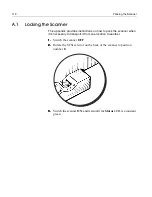
Страница 130: ...n how to pack the scanner when it is necessary to transport it from one location to another 1 1 1 1 Switch the scanner OFF 2 2 2 2 Rotate the SCSI selector on the back of the scanner to position numbe...

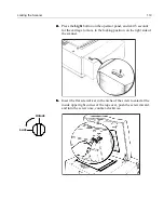
Страница 131: ...s for the carriage to move to the locking position on the right side of the scanner 5 5 5 5 Insert the flat screwdriver in the niche of the screw located at the inside upper right corner of the top co...

Страница 132: ...120 Packing the Scanner 6 6 6 6 Insert the flat screwdriver in the niche of the screw located on the right hinge of the top cover and turn the screw once clockwise Lock Unlock...

Страница 133: ...Packing the Scanner 121 A 2 Packing the Scanner 1 1 1 1 Place the accessory packages on the wooden palette...

Страница 134: ...carefully lift the scanner and place it on the wooden palette Make sure to place the scanner on the four bumpers located at the four corners of the palette and according to the markings on the bumper...

Страница 135: ...anner 123 3 3 3 3 Place the carton carefully over the scanner 4 4 4 4 Insert the four foam corners in the space between the scanner corners and the outer carton these are required to prevent movement...

Страница 136: ...124 Packing the Scanner 5 5 5 5 Place the upper cover protecting the scanner 6 6 6 6 Close the top cover and tape the carton 7 7 7 7 Use straps to attach the wooden palette to the carton...

Страница 137: ...125 Appendix B Technical Specifications...

Страница 138: ...DPI 125 DPM EverSmart Pro EverSmart Pro II 2540 DPI 100 DPM EverSmart Auto Focus Range From glass up to 5 mm Input Scanning Area 305 x 432 mm 12 x 17 in Original Types Transparent positive and negati...

Страница 139: ...ns Interface SCSI Electrical Requirements Input Power Voltage 100 240 VAC 50 60 Hz voltage selection is automatic Power Consumption 290 W operation 200 W standby Dimensions HxWxD 36 x 87x 70 cm 14 x 3...

Страница 140: ......

Страница 141: ...29 Appendix C Documentation Folder Documentation Folder 130 System Requirements for Using the Documentation 131 Installing Adobe Acrobat Reader on Macintosh 132 Using Adobe Acrobat Search Function 132...

Страница 142: ...documents are in Adobe Acrobat PDF file format so you need to install Adobe Acrobat Reader version 3 0 Installation instructions are included in this appendix The EverSmart Doc folder contains the fo...

Страница 143: ...PDF file format In order to view or print these files you must have the Adobe Acrobat Reader installed Installation instructions are provided below C 1 1 System Requirements for Using the Documentati...

Страница 144: ...you would like to search for in the Find Results Containing box 8 8 8 8 Click Search 9 9 9 9 The Search Results window appears containing a list of books where your word was found Select which book y...

Страница 145: ...133 Appendix D Application Log Files...

Страница 146: ...4 4 4 4 Send the created EverSmart Scan_Log Folder to your service center After the final scan the application log files will be created in the EverSmart Scan_Log Folder Every time you enter the scan...

Страница 147: ...135 Appendix E Catalog Numbers...

Страница 148: ...n slide pack type II 509D1L014A Scanner software 501V1N901 Screw Driver 395A10015 Mask pack 35 mm framed 1 piece 509D1L294 Mask pack User defined 10 pieces 509D1L005 Mask pack Mix format 5 pieces 509D...

Страница 149: ...3 501V50762 Optional EverSmart DOT for EverSmart Pro 510K51177 EverSmart DOT for EverSmart Pro II EverSmart Supreme 510K51893 Oil Mounting Station 510B44937 A star that appears after the catalog numbe...

Страница 150: ......

Страница 151: ...Warning notice 16 power 12 16 SCSI 3 31 calibration slide inserting 53 loading 72 misplaced troubleshooting 65 serial number location 48 50 calibration slide Important notice 59 card installation See...

Страница 152: ...02 maintenance 101 H horizontal lines troubleshooting 113 humidity 2 127 I ID selector SCSI 32 34 43 illumination 126 problems troubleshooting 114 image sensor 126 included kits 12 input voltage 2 16...

Страница 153: ...MatchBuilder 26 maximum original thickness 126 minimum system requirements 4 misregistration troubleshooting 112 N no communication with scanner troubleshooting 112 O operating temperature 127 optic...

Страница 154: ...backing up 77 scanner quality troubleshooting 112 scanner weight 127 scanner application hangs toubleshooting 114 scanning area 126 SCSI bus 43 cable 3 31 SCSI boards 3 installation 35 installation W...

Страница 155: ...it 83 lamps low light level 83 88 114 optics check out of tolerance 66 power self tests 110 scanner application hangs 114 scanning quality 112 SCSI communication failure 63 SCSI communication problems...

Отзывы: