background image

3-34


Removal and Replacement Procedures

Lithium Battery

When replacing a battery, use a Renata CR2032 or equivalent 3-volt lithium coin cell battery.

WARNING:  The system board contains a lithium-ion battery pack. There is a risk
of fire and chemical burn if the battery pack is handled improperly. Do not
disassemble, crush, puncture, short external contacts, dispose in water or fire, or
expose it to termperatures higher than 60ºC (140ºF).

NOTE:  It is important to make a diagnostics diskette before you install a new battery. Refer to
“Creating a Diagnostics Diskette” in Chapter 4 for more information.

To replace the lithium battery:

CAUTION:  Before removing the access panel, ensure that the workstation is
turned off, all cables are disconnected from the back of the workstation, and the
power cord is disconnected from the grounded AC outlet.

CAUTION:  Static electricity can damage the electronic components of the
workstation. Before beginning these procedures, be sure you are discharged of
static electricity by briefly touching a grounded metal object.

1.


Perform the service preparations shown on page 3-2.

2.


Remove the access panel.

3.


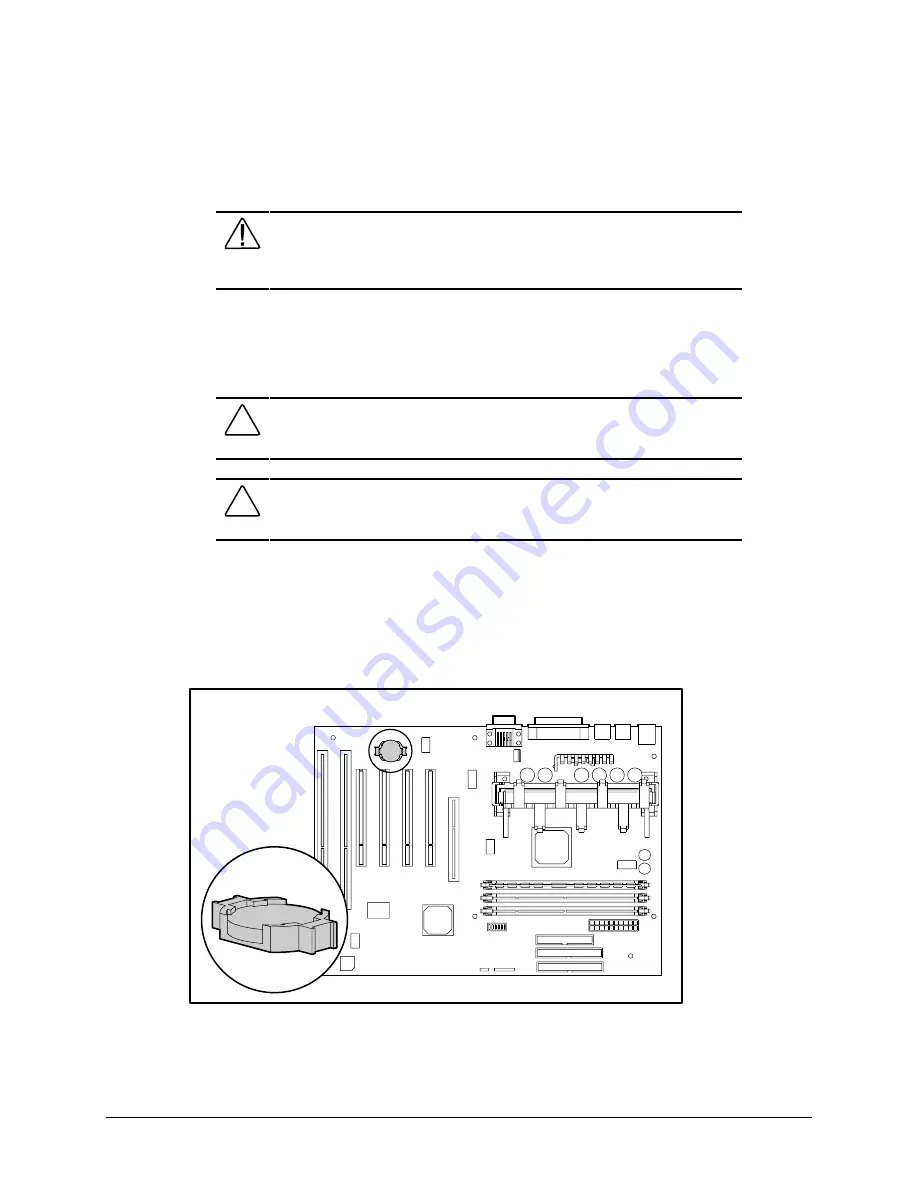
Locate the battery on the system board.

NOTE:  If you have expansion boards installed, you may need to remove them in order to gain
access to the battery.

Figure 3-35.  Locating the battery on the system board

Содержание Professional Workstation AP200

Страница 1: ...mpaq Professional Workstation AP200 Maintenance and Service Guide Professional Workstation AP200 Maintenance and Service Guide First Edition July 1998 Part Number 352624 001 Compaq Computer Corporatio...

Страница 2: ...form without prior written consent from Compaq Computer Corporation 1998 Compaq Computer Corporation All rights reserved Printed in the U S A The software described in this guide is furnished under a...

Страница 3: ...Warranty Information 2 4 Chapter 3 Removal and Replacement Procedures Serial Number 3 1 Service Preparations 3 2 Logo Plate 3 2 Cable Lock 3 3 Access Panel 3 4 Front Bezel 3 5 Subpanel and Bezel Blan...

Страница 4: ...rinter Problems 4 11 Hard Drive Problems 4 12 Hardware Installation Problems 4 13 CD ROM Drive IDE Problems 4 14 Memory Problems 4 15 SCSI Problems 4 15 Network Problems 4 16 Audio Hardware Conflicts...

Страница 5: ...6 3 Hard Drives 6 4 9 1 GB Wide Ultra SCSI Hard Drive 6 4 4 3 GB Wide Ultra SCSI Hard Drives 6 5 8 4 GB Ultra ATA Hard Drive 6 7 6 4 GB Ultra ATA Hard Drives 6 8 32X Max CD ROM Drive IDE 6 10 Chapter...

Страница 6: ...modifications to any printed wiring board Improper repairs can create a safety hazard Any indications of component replacement or printed wiring board modifications may void any warranty WARNING To re...

Страница 7: ...ice Training Guides Compaq Service Advisories and Bulletins Compaq QuickFind Compaq Insight Management Workstation Agents Compaq Download Facility Call 1 281 518 1418 Telephone Numbers For the name of...

Страница 8: ...trated Parts Catalog This chapter provides an illustrated parts breakdown and a reference for spare parts for the Compaq Professional Workstation AP200 Mechanical Parts 59d 59f 1 3 59i 59g 2 58a 2 59e...

Страница 9: ...2 Illustrated Parts Catalog System Components 38 41 44 11 7 8 9 10 59c 4 13 18 16 15 17 23 14 22 19 21 6 3 25 24 Figure 1 2 Exploded view of the Compaq Professional Workstation AP200 system component...

Страница 10: ...W 166814 001 7 System board 352648 001 8 Intel Pentium II Processor 350 100 MHz 512K with heat sink 166874 001 9 Intel Pentium II Processor 400 100 MHz 512K with heat sink 166882 001 10 Intel Pentium...

Страница 11: ...CD ROM drive IDE 327659 001 CABLE KITS 24 Miscellaneous Cable Kit 166838 001 288489 002 247116 001 242947 001 166879 001 25 SCSI cable 297511 001 26 SCSI LED cable 247485 001 27 NIC WOL cable 166974 0...

Страница 12: ...mpaq Fast Autosensing Ethernet NIC NC 3121 323556 001 SOFTWARE 45 Magellan Driver CD 297863 001 46 Spaceball Driver CD 298033 001 47 Microsoft Windows NT Workstation 4 0 CD 275573 xx1 48 Compaq SmartS...

Страница 13: ...athead screw 4 h plastic push lock fastener for fan assembly 4 166877 001 59 Miscellaneous plastics kit minitower and desktop includes a diskette bezel b rubber feet 8 c processor retainer with pins d...

Страница 14: ...chapter identifies the following service considerations Preliminary cautions and warnings Electrostatic discharge information Equipment symbols Tools and software requirements Warranty information IMP...

Страница 15: ...the complexity of the individual boards and subassemblies no one should attempt to make repairs at the component level or to make modifications to any printed wiring board Improper repairs can create...

Страница 16: ...d touching pins leads or circuitry Always place drives PCB assembly side down Use conductive field service tools Equipment Symbols The following symbols are located on applicable components of the wor...

Страница 17: ...y that extends the Compaq three year limited warranty by applying it to critical system components before they fail This warranty ensures that when you receive notification of a prefailure condition t...

Страница 18: ...omputer serial number to Compaq whenever you request information or order spare parts The serial number is located on the top corner of the workstation 1and also on the rear of the chassis 2 For asset...

Страница 19: ...tion IMPORTANT On a power managed system the power cord MUST be disconnected from the grounded AC outlet 3 Turn off all peripheral devices and disconnect cables from the rear of the workstation NOTE F...

Страница 20: ...ching a padlock and or cable lock If installed the locks must be removed before accessing internal components To remove the lock 1 Unlock and remove the cable lock and or the padlock 2 Remove the secu...

Страница 21: ...the back of the workstation and the power cord is disconnected from the grounded AC outlet 1 Perform the service preparations shown on page 3 2 2 Remove the two thumb screws that secure the access pa...

Страница 22: ...om the grounded AC outlet 1 Perform the service preparations shown on page 3 2 2 Remove the access panel 3 Press in on the two release tabs 1 then rotate the front bezel away from the chassis to remov...

Страница 23: ...power cord is disconnected from the grounded AC outlet 1 Perform the service preparations shown on page 3 2 2 Remove the access panel 3 Remove the front bezel 4 Gently pull the subpanel with the bezel...

Страница 24: ...ht CD ROM optional drive 1 6 inch 3 3 5 inch bay Third Height Standard 1 44 MB diskette drive 1 0 inch High density diskette drive is mounted with a drive adapter into a 5 25 inch bay 4 3 5 inch bay T...

Страница 25: ...the secondary controller IMPORTANT You must install guide screws to ensure the drives line up correctly in the drive cage Compaq has provided extra guide screws installed in the front of the workstati...

Страница 26: ...e workstation is turned off all cables are disconnected from the back of the workstation and the power cord is disconnected from the grounded AC outlet 1 Perform the service preparations shown on page...

Страница 27: ...o guide screws from each side of the drive To replace the 3 5 inch hard drive install two guide screws on each side of the replacement drive be sure the guide screws line up with the guide slots and s...

Страница 28: ...adapter bracket Refer to Chapter 1 for the spare part number To remove a 3 5 inch drive with a 5 25 inch drive adapter CAUTION Before removing the access panel ensure that the workstation is turned of...

Страница 29: ...adapter by squeezing in on both sides then rotate the brace up and out 2 8 Remove the drive bezel 3 9 Remove the screws that secure the drive to the drive adapter 4 10 Remove the drive from the drive...

Страница 30: ...workstation is turned off all cables are disconnected from the back of the workstation and the power cord is disconnected from the grounded AC outlet 1 Perform the service preparations shown on page 3...

Страница 31: ...k 6 While pressing the drivelock pull the drive out of the drive bay Figure 3 17 Removing a 5 25 inch drive To replace the drive install two guide screws on each side of the replacement drive in the b...

Страница 32: ...t the communication between the controller and the SCSI device The reserced and available SCSI ID numbers for SCSI devices are as follows SCSI ID 0 is reserved for the primary hard drive SCSI ID 7 is...

Страница 33: ...your workstation may look slightly different than the one pictured The SCSI cable illustrated above supports up to 4 SCSI devices and comes with a terminator 1on the end NOTE If you are installing a n...

Страница 34: ...ock positions To remove the drivelocks CAUTION Before removing the access panel ensure that the workstation is turned off all cables are disconnected from the back of the workstation and the power cor...

Страница 35: ...ing the drivelock To reinstall the drivelock 1 Insert the left side of the drivelock with the rounded tabs into the slots on the drive cage 2 Place the washer on the middle tab on the underside of the...

Страница 36: ...ts See the corresponding table for component names 1 3 4 5 6 2 Figure 3 22 Overview of expansion slots Table 3 2 Expansion Slots Reference 1 ISA slot audio card installed 2 Combination slot for either...

Страница 37: ...d is disconnected from the grounded AC outlet 1 Perform the service preparations shown on page 3 2 2 Remove the access panel 3 Disconnect any cables from the expansion board 4 Remove the expansion boa...

Страница 38: ...n page 3 2 2 Remove the access panel 3 Disconnect any cables from the graphics controller 4 Remove the retaining screw that secures the graphics controller 5 Hold the graphics controller at each end a...

Страница 39: ...kstation and the power cord is disconnected from the grounded AC outlet 1 Perform the service preparations shown on page 3 2 2 Remove the access panel 3 Remove any full length expansion boards 4 Push...

Страница 40: ...n DIMMs constructed with x4 SDRAM are not supported the system will not start using unsupported DIMMs DO NOT MIX REGISTERED AND UNREGISTERED OR ECC AND NON ECC SDRAM DIMMS OTHERWISE THE SYSTEM WILL NO...

Страница 41: ...board that support up to a maximum of 384 MB The following illustration identifies the physical location of all DIMM sockets Note that DIMMs do not need to be installed in pairs and can be installed i...

Страница 42: ...rd on both latches of the DIMM at the same time 1 This releases the module and pushes it partially out of the socket 4 Lift the module from the socket 2 2 1 1 Figure 3 27 Removing a memory module NOTE...

Страница 43: ...ed AC outlet 1 Perform the service preparations shown on page 3 2 2 Remove the access panel NOTE It may be necessary to remove the AGP graphics controller before removing the processor 3 Press in on t...

Страница 44: ...urned off all cables are disconnected from the back of the workstation and the power cord is disconnected from the grounded AC outlet 1 Perform the service preparations shown on page 3 2 2 Remove the...

Страница 45: ...workstation and the power cord is disconnected from the grounded AC outlet 1 Perform the service preparations shown on page 3 2 2 Remove the access panel 3 Disconnect the speaker cable from the audio...

Страница 46: ...is disconnected from the grounded AC outlet NOTE The system fan is integrated into the power supply 1 Perform the service preparations shown on page 3 2 2 Remove the access panel 3 Disconnect all pow...

Страница 47: ...signed for connection to a grounded earthed outlet The grounding type plug is an important safety feature To reduce the risk of electrical shock damage to the equipment or loss of the data do not disa...

Страница 48: ...les are disconnected from the back of the workstation and the power cord is disconnected from the grounded AC outlet 1 Perform the service preparations shown on page 3 2 2 Remove the access panel 3 Di...

Страница 49: ...the grounded AC outlet 1 Perform the service preparations shown on page 3 2 2 Remove the access panel 3 Remove all expansion boards 4 Disconnect all cables that are attached to the system board 5 Rem...

Страница 50: ...of the workstation and the power cord is disconnected from the grounded AC outlet 1 Perform the service preparations shown on page 3 2 2 Remove the access panel 3 Remove all expansion boards 4 Disconn...

Страница 51: ...apter 4 for more information To replace the lithium battery CAUTION Before removing the access panel ensure that the workstation is turned off all cables are disconnected from the back of the workstat...

Страница 52: ...battery out of the holder Figure 3 36 Removing the battery To replace the battery slide the replacement battery into position with the positive side up IMPORTANT Positive polarity should be positioned...

Страница 53: ...bles are disconnected from the back of the workstation and the power cord is disconnected from the grounded AC outlet 1 Perform the service preparations shown on page 3 2 2 Remove the access panel 3 R...

Страница 54: ...es then reinstall them into the drive bays IMPORTANT The diskette drive should always be placed in the bay nearest the top of the chassis in the desktop configuration for proper drive clearance and ac...

Страница 55: ...ou pull it away from the front bezel Pulling the subpanel away at an angle could damage the pins that align it within the front bezel Desktop Configuration Minitower Configuration Figure 3 39 Rotating...

Страница 56: ...turned off all cables are disconnected from the back of the workstation and the power cord is disconnected from the grounded AC outlet 1 Perform the service preparations shown on page 3 2 2 Remove the...

Страница 57: ...stall them into the drive bays IMPORTANT The diskette drive should always be placed in the bay 3 the bay nearest the internal 3 5 inch drives for proper placement within the chassis Figure 3 41 Instal...

Страница 58: ...l straight when you pull it away from the front bezel Pulling the subpanel away at an angle could damage the pins that align it within the front bezel Desktop Configuration Minitower Configuration Fig...

Страница 59: ...n servicing the Compaq Professional Workstation AP200 Power On Self Test POST Troubleshooting Minor Problems Computer Setup and Diagnostics Utilities Error Codes ROMPaq Compaq Insight Manager Compaq S...

Страница 60: ...rive Hard drives Processors Controllers POST also detects the type of SCSI mass storage devices installed in the workstation NOTE If the Power On Password is set a key icon appears on the screen while...

Страница 61: ...imately 5 years CMOS jumper may not be properly installed Run Computer Setup or Windows NT utilities First reset the date and time under Control Panel If the problem persists replace the RTC battery S...

Страница 62: ...essage is missing critical SPD information or is incompatible with the chipset Replace the DIMM with a module conforming to the SPD standard 301 Keyboard Error None Keyboard failure Reconnect keyboard...

Страница 63: ...Address Assignment Conflict 2S Both external and internal serial ports are assigned to COM2 Run Computer Setup or Windows NT utilities 1155 System Board COM Port Address Assignment Conflict 2S COM po...

Страница 64: ...y Check 2 None Parity RAM failure Run the Setup and Diagnostics utilities A Correctable Memory error Occurred prior to this Power Up None Single bit ECC error during previous POST 1 Run Computer Setup...

Страница 65: ...hold any key If the system beeps the keyboard should be operating correctly Are all of the necessary device drivers installed Have all printer drivers been installed for each application Was a nonboo...

Страница 66: ...s from the workstation s power supply are plugged in properly A PCI or ISA card that has been installed is not seated properly or is defective Be sure that the card is fully inserted or remove the PCI...

Страница 67: ...ther diskette that is not write protected or disable the write protection on the diskette 3 Writing to the wrong drive Check the drive letter in the path statement 4 Not enough space is left on the di...

Страница 68: ...re is a sync switch set it to External 8 If a fixed sync monitor is used be sure that the monitor can accept the same sweep rate as the resolution chosen 9 Check that the graphics adapter is fully and...

Страница 69: ...s the Num Lock key The Num Lock light should not be on when you want to use the arrow keys Printer Problems This section identifies some quick checks for printer related problems Table 4 5 Solutions f...

Страница 70: ...Problem Possible Solution Hard drive error occurs Hard disk has bad sectors or has failed Use a utility to locate and block usage of bad sectors If necessary reformat the hard disk Disk transaction p...

Страница 71: ...ave automatically recognized the new device Run Computer Setup and identify the new device 4 A Plug and Play board may not automatically configure when added if the default configuration conflicts wit...

Страница 72: ...M boot is not enabled through the Computer Setup utility Run the Computer Setup utility and set the drive priorities 2 Be sure that drive cabling and jumpers are set correctly Cannot eject compact dis...

Страница 73: ...DIMMs may not be installed correctly Check that the DIMMs have been installed correctly in the DIMM sockets then run the Computer Setup utility Insufficient memory error during operation The system h...

Страница 74: ...roller interrupt or memory overlaps the interrupt or memory of an expansion board 1 Be sure the cable is securely attached to the network connector and that the other end of the cable is securely atta...

Страница 75: ...working without apparent cause 1 The files containing the network drivers are corrupted 2 The cable is not securely connected 3 The network controller is defective 1 Reinstall the network drivers the...

Страница 76: ...P200 and is shipped in English only To access the Computer Setup menu 1 Turn on or restart the workstation NOTE Do not restart the workstation while in Windows NT Workstation Instead exit Windows NT W...

Страница 77: ...tations Home Page click Manual System Configuration 4 Click Install Optional Compaq Software 5 Click Create a Diagnostics Diskette 6 Follow the instructions on the screen Running Computer Checkup TEST...

Страница 78: ...f the list is correct select OK The test option menu is displayed again If the list is incorrect be sure that any new devices are installed properly NOTE This utility may not detect non Compaq devices...

Страница 79: ...M System storage System ports Current memory configuration ROM version Type of processor and coprocessor Diskette CD ROM and hard drives Active printer and communications interfaces Keyboard Graphics...

Страница 80: ...ch 15 cm clearance at the rear of the chassis 2 Turn off the workstation and peripheral devices CAUTION Always be sure the power is off before disconnecting or reconnecting the mouse keyboard or any o...

Страница 81: ...x Keyboard controller self test failed Replace the system board and retest 107 xx CMOS RAM test failed The following steps apply to error codes 107 xx through 109 xx 108 xx CMOS interrupt test failed...

Страница 82: ...at a time testing each to ensure the error does not return 211 xx Random pattern test failed 3 Replace the system board and retest 214 xx Noise test failed 215 xx Random address test failed Keyboard...

Страница 83: ...xx Diskette ID drive types test failed The following steps apply to error codes 600 xx through 698 xx 601 xx Diskette format failed 1 Replace the diskette media and retest 602 xx Diskette read test f...

Страница 84: ...h 1210 xx 1202 xx Modem time out test failed 1 Disconnect from the phone line and retest 1203 xx Modem external termination test failed 2 Check the phone number 1204 xx Modem auto originate test faile...

Страница 85: ...cables and retest 6608 xx Controller test failed 5 Replace the CD ROM drive and retest 6623 xx Random read test failed Tape Drive Table 4 21 Tape Drive Test Error Codes Error Code Description Recommen...

Страница 86: ...x Video 320 200 mode color set 1 test failed 510 xx Video 640 200 mode test failed 511 xx Video screen memory page test failed 512 xx Video gray scale test failed 514 xx Video white screen test failed...

Страница 87: ...C 640 200 graphics mode test failed 2422 xx ECG VGC 640 350 16 color set test failed 2423 xx ECG VGC 640 350 64 color set test failed 2424 xx ECG VGC monochrome text mode test failed 2425 xx ECG VGC m...

Страница 88: ...codes 6000 xx through 6089 xx 6014 xx Network configuration test failed 1 Turn the workstation off then on cold boot and run Computer Setup or Windows NT utilities 6016 xx Network reset test failed 2...

Страница 89: ...example if you received a diagnostic error code of 6523 05 you would look at Table 4 25 to identify the meaning of the first two numbers 65 This indicates a hard drive problem The second set of two n...

Страница 90: ...protected 1 Disable write protect on tape cartridge 2 Replace tape drive XXXX 18 No data detected Replace the indicated device XXXX 21 Drive command aborted Replace the indicated device 65XX 24 Media...

Страница 91: ...dicated device XXXX 52 MSG C D and or I O lines bad Replace the indicated device XXXX 53 BSY never went busy Replace the indicated device XXXX 54 BSY stayed busy Replace the indicated device XXXX 60 C...

Страница 92: ...st be set See Chapter 5 for procedures on establishing a Setup Password 2 If prompted enter the Setup Password NOTE If the Setup Password is entered correctly the ROMPaq utility will take over and run...

Страница 93: ...MPORTANT The workstation ships with the Diskette Boot feature enabled If the Diskette Boot feature is disabled the FailSafe Boot Block ROM will override the disabled feature to accommodate a system RO...

Страница 94: ...board Lights Num Lock Caps Lock Scroll Lock Meaning and Required Action OFF ON OFF System requires Setup Password Enter the Setup Password The light remains turned on until you enter a valid Setup Pas...

Страница 95: ...ation instructions in the Workstation Software Reference Addendum in the Compaq Information Center folder or on the SmartStart for Workstations CD For more detailed instructions about setting up SNMP...

Страница 96: ...ith the workstation contains the following support software drivers Network controller driver SCSI controller driver Compaq HAL for Microsoft NT 3 51 ELSA display driver ESS 1869 AudioDrive driver IMP...

Страница 97: ...ry names appear near the cursor 3 To display more detailed information in a selected category click More in the Information Level box 4 Categories or items of information displayed by Compaq Diagnosti...

Страница 98: ...restarted unless the power on password is entered Computer Setup menu Windows NT for Workstations Password Prevents use of the computer when Windows NT starts up unless the password is entered Run Us...

Страница 99: ...on the workstation 2 When the F10 Setup message appears in the lower right corner of the screen press F10 NOTE You have approximately two seconds to press F10 If you do not press F10 during this time...

Страница 100: ...ew the current computer settings press Enter Changing a Setup or Power On Password To change the Setup or Power On Password 1 Turn on the workstation 2 To change the Setup Password run Computer Setup...

Страница 101: ...ration settings You may view the current settings but you may not change them unless you know the Setup or Power On Password To clear the Setup or Power On Password 1 Turn off the workstation 2 Remove...

Страница 102: ...r National Keyboard Delimiter Characters Each keyboard is designed to meet country specific requirements The syntax and keys you use for changing or deleting the password depend on the keyboard that c...

Страница 103: ...ough the Computer Setup menu Storage under Built in Devices Disable removable media boot ability Disable removable media write ability Communication under Built in Devices Disable serial port Disable...

Страница 104: ...right arrow keys to select Enable 6 Save the configuration and exit the utility 7 Restart the workstation IMPORTANT If you disable the diskette drive the FailSafe Boot Block ROM will ignore the disab...

Страница 105: ...ower On Password established in Security To enable the QuickLock and QuickBlank features from the Computer Setup menu 1 Turn on the workstation 2 When the F10 Setup message appears in the lower right...

Страница 106: ...yboard and input device connected to the mouse connector enter the password NOTE For security reasons the characters you type will not appear on the screen The application will not be affected by the...

Страница 107: ...switch information for the system board and disk drives for the Compaq Professional Workstation AP200 The components on the system board which is Pentium II based are illustrated in the following figu...

Страница 108: ...CI expansion slot 5 PCI expansion slot 6 AGP graphics controller slot 7 Fan connector not used on standard models 8 Processor connector 9 DIMM sockets 1 3 10 Power supply connector 11 IDE connector di...

Страница 109: ...tup Password S1 on switch 1 enables the Power On Password Setup Password The default is OFF To reset the password turn this switch ON ON 350 MHz 1 2 3 4 5 6 ON 450 MHz 1 2 3 4 5 6 ON 400 MHz 1 2 3 4 5...

Страница 110: ...Model J2 Default Settings Jumper NOT Installed Jumper Installed Key Signal S P W X Description Start Unit Command Enabled Parity Enabled Write Protect Disabled Synch Data Transfer Enabled Jumper n a P...

Страница 111: ...W X Description Start Unit Command Enabled Parity Enabled Write Protect Disabled Synch Data Transfer Enabled Jumper n a n a Pin 1 Bit 0 For Hot Pluggable Drive Tray connect SCSI ID Cable to this Conne...

Страница 112: ...rt Unit Command Enabled Parity Enabled Write Protect Disabled Synch Data Transfer Enabled Jumper n a Pin 1 J2 Bit 2 Bit 0 Bit 3 Bit 1 S P SCSI POWER Pin 1 J1B 1 All jumper and switch settings are show...

Страница 113: ...1 8 4 GB Drive Size ST38641A Model IDE Settings Configuration 5 6 Jumper NOT Installed Jumper Installed Key 3 5 2 4 6 3 4 1 2 Single Standard Installation Dual Master Dual Slave Cable Select Shipping...

Страница 114: ...ST36531A Model IDE Settings Configuration 5 6 Jumper NOT Installed Jumper Installed Key 3 5 2 4 6 3 4 1 2 Single Standard Installation Dual Master Dual Slave Cable Select Shipping Configuration Singl...

Страница 115: ...AC36400 60LC Model IDE Settings Configuration 5 6 Jumper NOT Installed Jumper Installed Key 3 4 1 2 Single Standard Installation Dual Master Dual Slave Cable Select Shipping Configuration Single Neutr...

Страница 116: ...6 10 Jumper and Switch Information 32X Max CD ROM Drive IDE C S M S L A C S M S L A C S M S L A Use CSEL Slave Master Figure 6 9 Jumper positions for the 32X Max CD ROM drive IDE...

Страница 117: ...l and Operating Specifications This chapter provides operating and performance specifications for the following Compaq Professional Workstation AP200 hardware System Unit Power Supply Diskette Drive C...

Страница 118: ...Range Rated Line Frequency Rated Input Current maximum 90 132 VAC 100 127 VAC 50 60 Hz 5 5 A 180 264 VAC 200 250 VAC 50 60 Hz 3 0 A Environmental Requirements Temperature Operating Shipping 50 to 95...

Страница 119: ...System timer IRQ 1 Keyboard Not on ISA Bus IRQ 2 Unused IRQ 3 Serial Port COM 2 IRQ 4 Serial Port COM 1 IRQ 5 Unused IRQ 6 Diskette Drive IRQ 7 Parallel Port LPT 1 IRQ 8 Real time clock IRQ 9 ESS sou...

Страница 120: ...4 DMA Controller Cascading Not on ISA Bus DMA 5 Unused DMA 6 Unused DMA 7 Unused Table 7 4 System I O I O Address Hex System Function Shipping Configuration 000 00F DMA Controller 1 010 01F Unused 01F...

Страница 121: ...0EB Unused 0EC 0ED 483 Configuration Index Data 0EE 0EF 483 Fast A20 Fast Reset 0F0 0F1 Co Processor Busy Clear Reset 0F2 0F3 Unused 0F4 0F5 483 CPU Speed Slow Fast 0F6 0F8 Unused 0F9 483 PGL Configur...

Страница 122: ...8 27F Reserved Parallel Port 280 2E7 Unused 2E8 2EF Reserved Serial Port 2F0 2F7 Unused 2F8 OFF Modem COM 2 300 317 Unused 318 319 Unused 31A 36F Unused 370 377 Reserved 2nd Diskette Drive 378 37F Par...

Страница 123: ...C Address Range FECFFFFFh to FEC00000h 1024 KB I O APIC Address Range C7FFFFFFh to 40000000h 2 228 224 KB PCI Memory Expansion 3FFFFFFFh to 01000000h 1 032 192 KB HOST Memory Expansion 00FFFFFFh to 00...

Страница 124: ...32 VAC 180 to 264 VAC Holdup Time 16 ms from zero crossing at 115 VAC 16 ms from zero crossing at 230 VAC Full Output Rating To 40 C and 5 000 ft To 32 C and 10 000 ft derate linearly Minimum Load 1 5...

Страница 125: ...nsity MB 1 44 Low Density KB 720 Light Green Height One third Bytes per Sector 512 Sectors per Track High Density 18 Low Density 9 Tracks per Side High Density 80 Low Density 80 Read Write Heads 2 Ave...

Страница 126: ...Disk Thickness 1 2 mm Track Pitch 1 6 m Performance Access Time Random Seek Full Stroke Seek 100 ms 150 ms Data Transfer Rate Sustained Burst 150 KB s 2100 to 4800 KB s 14x to 32x variable Bus Rate 4...

Страница 127: ...Response 0 7 Vrms 80 dB 65dB 0 1 20 to 20 kHz Digital Audio Out Connector 2 pin digital audio out connector described in the ATAPI spec 2 6 section 11 1 must be included This serial digital audio out...

Страница 128: ...dia 13 6 to 21 3 MB s Asynchronous 5 0 MB s Synchronous Up to 40 0 MB s Seek Time typical Single Track 1 6 ms Average 7 5 ms Full Stroke 15 0 ms Disk Rotation Speed 7200 rpm Cylinders 8419 Data Heads...

Страница 129: ...er Rate Media 13 6 to 21 3 MB s Asynchronous 5 0 MB s Synchronous Up to 40 0 MB s Seek Time typical Single Track 1 6 ms Average 7 5 ms Full Stroke 15 0 ms Disk Rotation Speed 7200 rpm Cylinders 8419 D...

Страница 130: ...soft Transfer Rate Media 83 to 140 MB s Interface 33 MB s Seek Time typical Single Track 1 7 ms Average 11 5 ms Full Stroke 20 2 ms Disk Rotation Speed 5400 rpm Cylinders 16383 Data Heads Logical 16...

Страница 131: ...Type 65 soft Transfer Rate Media 83 to 140 MB s Interface 33 3 MB s Seek Time typical Single Track 2 0 ms Average 9 5 ms Full Stroke 20 0 ms Disk Rotation Speed 5200 to 5400 rpm Cylinders 13328 Data H...

Страница 132: ...ecord 83 dB 81 dB 78 dB Total Harmonic Distortion 0 060 Frequency Response 3 dB cutoffs Line Level 48 Khz Speaker 20 Hz to 20 000 Hz 110 Hz to 15 000 Hz Impedence nominal Microphone in Line in Headpho...

Страница 133: ...Base Resolution 400 dpi Tracking Speed maximum 10 in sec 25 cm sec Temperature Operating Storage 32 F to 104 F 4 F to 140 F 0 C to 40 C 20 C to 60 C Lifetime Mechanical Switch Exceeds 300 miles Excee...

Страница 134: ...imum Refresh Rate 1920 x 1200 256 32 768 75 Hz 1920 x 1080 256 32 768 80 Hz 1600 x 1280 32 768 32 768 75 85 Hz 1600 x 1200 32 768 32 768 85 Hz 1600 x 1000 32 768 32 768 100 Hz 1536 x 1152 32 768 32 76...

Страница 135: ...rating Environment Temperature Humidity 50 to 95 F 10 to 35 C 10 to 90 noncondensing Electrical Bus 32 bit PCI bus RJ 45 Network Cable Specifications The RJ 45 connections use an unshielded twisted pa...

Страница 136: ...e physical location of each connector Refer to corresponding table for connector names 1 2 3 4 5 6 9 10 11 7 8 12 14 13 15 Figure 8 1 Overview of external connectors Table 8 1 External Connectors Refe...

Страница 137: ...ice such as a serial printer COM 2 B on top COM 1 A on bottom 9 Video Port AGP Connects a monitor 10 External SCSI connector Connects a SCSI device 11 RJ 45 connector Connects to the Ethernet network...

Страница 138: ...Assignments Table 8 2 Keyboard Connector and Icon Orange Pin Signal 188368bd AI KEYBD EPS 1 2 4 6 3 5 1 2 3 4 5 6 Data Unused Ground 5 VDC Clock Reserved Table 8 3 Mouse Connector and Icon Green Pin S...

Страница 139: ...1 12 13 14 15 16 17 18 19 20 21 22 23 24 25 Pin Signal 1 2 3 4 5 6 7 8 9 10 11 12 13 14 15 16 17 18 25 Strobe Data Bit 0 Data Bit 1 Data Bit 2 Data Bit 3 Data Bit 4 Data Bit 5 Data Bit 6 Data Bit 7 Ac...

Страница 140: ...ce and Service Guide Table 8 5 Serial Interfaces Connector and Icon Pin Signal 1 2 3 4 5 6 7 8 9 1 2 3 4 5 6 7 8 9 Carrier Detect Receive Data Transmit Data Data Terminal Ready Signal Ground Data Set...

Страница 141: ...15 14 13 12 11 1 2 3 4 5 6 7 8 9 10 11 12 13 14 15 Red Analog Green Analog Blue Analog Monitor ID Bit 2 Ground Ground Analog Ground Analog Ground Analog Not Connected Ground Monitor ID Bit 0 Bi direc...

Страница 142: ...Guide Table 8 7 Ethernet RJ 45 Connector and Icon Pin Signal 1 3 5 7 2 4 6 8 1 2 3 4 5 6 7 8 Transmit Data Transmit Data Receive Data Unused Unused Receive Data Unused Unused Table 8 8 USB Connector...

Страница 143: ...1 16 17 18 19 20 34 35 36 37 38 39 40 41 42 43 44 45 46 47 48 49 50 Ground TERMPWR Reserved Ground D12 D13 D14 D15 DP1 D0 D1 D2 D3 D4 D5 D6 D7 DP0 Ground 51 52 53 54 55 56 57 58 59 60 61 62 63 64 65...

Страница 144: ...n Connector Connector and Icon Stereo 1 8 inch Miniphone Table 8 11 Audio Line Out Connector Connector and Icon Stereo 1 8 inch Miniphone Table 8 12 Microphone Connector Connector and Icon Blue Stereo...

Страница 145: ...rt number 1 3 access panel removing 3 4 adapter drive 3 11 advanced security management 5 6 AGP See Accelerated Graphics Port AGP AGP graphics controller connector 8 2 spares part number 1 5 location...

Страница 146: ...eting a Power On password 5 4 deleting a setup password 5 4 delimiter characters 5 5 desktop configuration installing a drive 3 37 desktop to minitower converting 3 41 diagnostic error codes 4 22 audi...

Страница 147: ...attery spares part number 1 3 external connectors functions 8 1 physical locations 8 1 external SCSI connector 8 2 pin assignments 8 8 F FailSafe Boot Block ROM 4 35 Flash recovery diskette obtaining...

Страница 148: ...onnector pin assignments 8 9 lithium battery location 3 34 removing 3 35 Local ROM Flash 4 34 locating the SW1 switch 5 4 lock security bracket spares part number 1 3 logo plate removing 3 2 M Magella...

Страница 149: ...parts mechanical 1 1 1 3 illustrated 1 1 password Microsoft Windows NT Workstation 5 5 Power On 5 2 Power On key icon 4 2 setup 5 2 Windows NT Workstation 5 5 PCI locations 3 19 Pentium II processor...

Страница 150: ...M drive cables 3 13 disconnecting hard drive cables 3 9 drivelock 3 18 drivelock reinstalling 3 18 expansion board 3 20 removal and replacement continued front bezel 3 5 I O panel 3 33 Intel Pentium I...

Страница 151: ...llustrated 1 1 system components exploded view illustrated 1 2 spares part number 1 2 height mounting bracket 1 5 128 MB memory module 1 3 16 MB memory module 1 3 32 MB memory module 1 3 32X Max CD RO...

Страница 152: ...DMA 7 4 I O addresses 7 4 interrupts 7 3 system board spares part number 1 3 switch settings 6 3 system board components 6 2 AGP graphics controller slot 6 2 CD ROM drive connector 6 2 CMOS header 6 2...

Страница 153: ...8 6 video test error codes 4 28 View System Information INSPECT 4 21 running 4 21 voltage selector switch 8 1 W warnings 2 2 warranty extended 2 4 prefailure 2 4 standard 2 4 website Compaq vii wide...

Отзывы: