


InteliMains 210 Global Guide
126
Locate the mouse pointer over the starting point of the wire. If the area under the mouse pointer is a
connection point, the pointer will change the color (fill of pointer will be white).
Press and hold the left mouse button and drag the wire to the destination of required connection point. If you
point over a valid connection point, the connection point will be marked with a red circle.
Release the left mouse button to create a wire between the two points. The wire is routed automatically.
Note:
It is possible to make connection only between the outputs and inputs with the same type of value (binary
or analog). Binary values are marker by black pointer, analog values are marked with green pointer.
Note:
To delete wire just click on it and press delete button. Also delete selection function can by used.
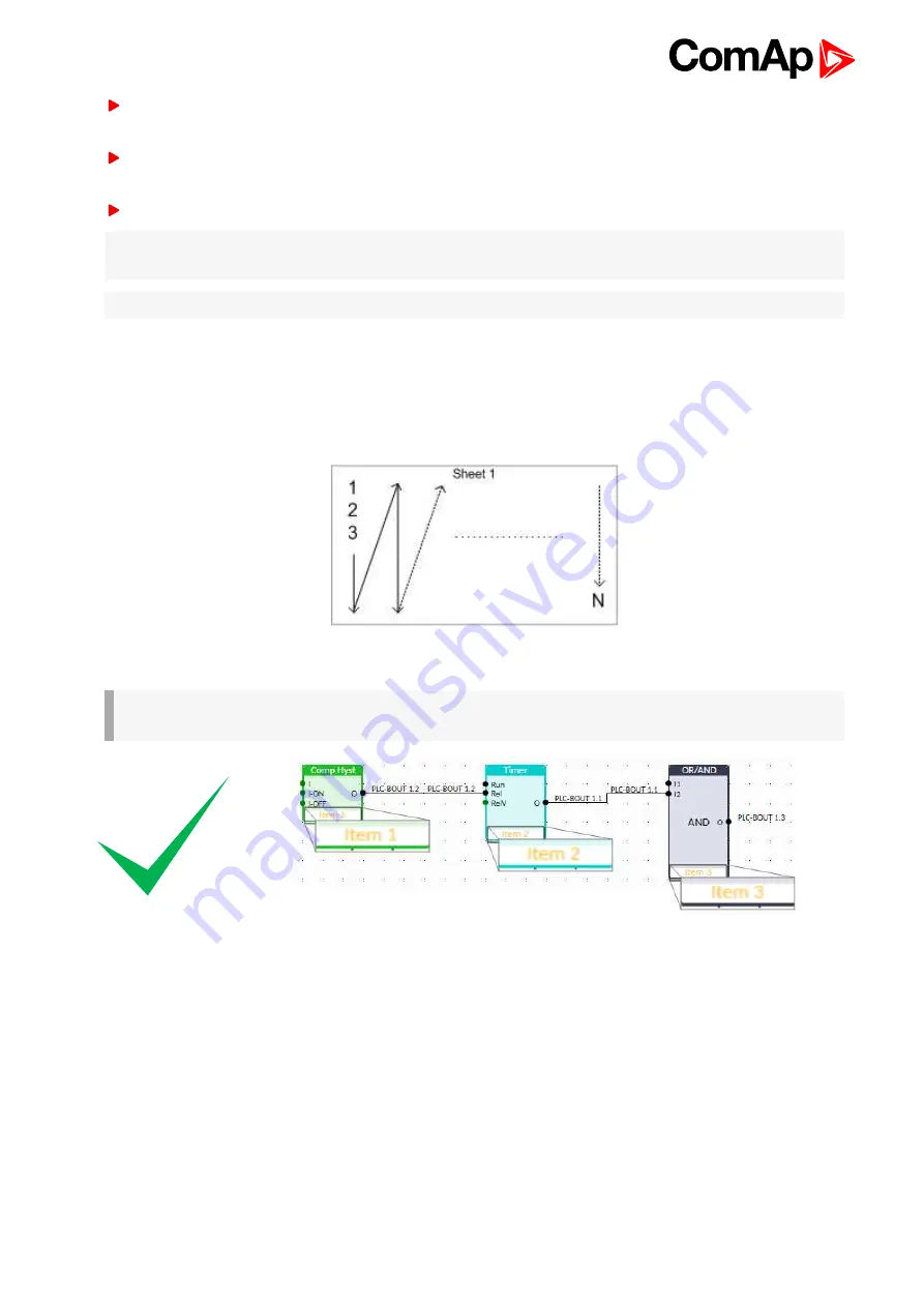
PLC logic execution rules
The PLC program is executed every 100 ms. The blocks are executed in order according to block numbers (item
numbers), which are indicated in each block. The block numbers are assigned automatically according to
position on sheet.
Image 5.51 PLC execution logic
IMPORTANT: Please always check that the blocks are ordered correctly, especially if you use direct
feedbacks from outputs to inputs within one sheet. Wrong order may lead to incorrect results!!!
Содержание InteliMains 210 BTB
Страница 169: ...PLC Setpoint 61 360 PLC Setpoint 62 361 PLC Setpoint 63 362 PLC Setpoint 64 363 InteliMains 210 Global Guide 169 ...
Страница 366: ...Log Bout 6 385 Log Bout 7 386 Date Time Time 394 Date 394 InteliMains 210 Global Guide 366 ...
Страница 494: ...InteliMains 210 Global Guide 494 Image 8 144 Configuration of OR AND block 6 back to List of PLC blocks ...


