


58
Static Pressure Set Point (
SP.SP
) — This is the static pres-
sure control point. It is the point against which the
Comfort
Link controls compare the actual measured supply
duct pressure for determination of the error that is used for PID
control. Generally one would set
SP.SP
to the minimum value
necessary for proper operation of air terminals in the condi-
tioned space at all load conditions. Too high of a value will
cause unnecessary fan motor power consumption at part-load
conditions and/or noise problems. Too low a value will result in
insufficient airflow.
VFD Minimum Speed (
SP.MN
) — This is the minimum speed
for the supply fan VFD. Typically the value is chosen to main-
tain a minimum level of ventilation.
NOTE: Most VFDs have a built-in minimum speed adjustment
which must be configured for 0% when using
Comfort
Link
controls for static pressure control.
VFD Maximum Speed (
SP.MX
) — This is the maximum
speed for the supply fan VFD. This is usually set to 100%.
VFD Fire Speed Override (
SP.FS
) — This is the speed that
the supply fan VFD will use during the pressurization, evacua-
tion and purge fire modes. This is usually set to 100%.
Static Pressure Reset Configuration (
SP.RS
) — This option
is used to configure the static pressure reset function. When
SP.RS
= 0, there is no static pressure reset via an analog input.
If the outdoor air quality sensor is not configured (
Configura-
tion
IAQ
IAQ.CF
OQ.A.C
= 0), then it is possible to use
the outdoor air quality sensor location on the CEM board to
perform static pressure reset via an external 4 to 20 mA input.
Configuring
SP.RS
= 1 provides static pressure reset based
on this CEM 4 to 20 mA input and ranged from 0 to 3 in. wg.
Wire the input to the CEM using TB6-11 and 12. When
SP.RS
= 2, there is static pressure reset based on RAT and defined by
SP.RT
and
SP.LM
. When
SP.RS
= 3, there is static pressure re-
set based on SPT and defined by
SP.RT
and
SP.LM
.
Setting
SP.RS
to 1, 2 or 3 will give the user the ability to re-
set from 0 to 3 in. wg of static pressure. The reset will apply to
the supply static pressure set point. The static pressure reset
function will only act to reduce the static pressure control point.
As an example, the static pressure reset input is measuring
6 mA, and is therefore resetting 2 mA (6 mA – 4 mA) of its
16 mA control range. The 4 to 20 mA range corresponds
directly to the 0 to 3 in. wg of reset. Therefore 2 mA reset is
2/16 * 3 in. wg = 0.375 in. wg of reset. If the static pressure set
point (
SP.SP
) = 1.5 in. wg, then the static pressure control point
for the system will be reset to 1.5 – 0.375 = 1.125 in. wg.
When
SP.RS
= 4, the static pressure reset function acts to
provide direct VFD speed control where 4 mA = 0% speed and
20 mA = 100% (
SP.MN
and
SP.MX
will override). Note that
SP.CF
must be set to 1 (VFD Control), prior to configuring
SP.RS
= 4. Failure to do so could result in damage to ductwork
due to overpressurization. This is the recommended approach
if a third party wishes to control the variable speed supply fan.
In effect, this represents a speed control signal “pass through”
under normal operating circumstances. The
Comfort
Link con-
trol system overrides the third party signal for critical operation
situations, most notably smoke and fire control.
Static Pressure Reset Ratio (
SP.RT
) — This option defines
the reset ratio in terms of static pressure versus temperature.
The reset ratio determines how much is the static pressure
reduced for every degree below set point for RAT or SPT.
Static Pressure Reset Limit (
SP.LM
) — This option defines
the maximum amount of static pressure reset that is allowed.
This is sometimes called a “clamp.”
NOTE: Resetting static pressure via RAT and SPT is primarily
a constant volume application which utilizes a VFD. The rea-
soning is that there is significant energy savings in slowing
down a supply fan as opposed to running full speed with
supply air reset. Maintaining the supply air set point and
slowing down the fan has the additional benefit of working
around dehumidification concerns.
Static Pressure Reset Economizer Position (
SP.EC
) — This
option effectively resets ECONOMIN to fully occupied venti-
lation position, to account for the drop in static pressure during
static pressure reset control. The static pressure reset for the
calculation cannot be larger than the supply air static set point
(
SPSP
).
The calculation is as follows:
(Static Pressure Reset/
SP.LM
) x (ECONOSPR –
ECONOMIN)
As an example, the static pressure reset limit (
SP.LM
) =
0.75 in. wg. The current static pressure reset is set to 0.5 in. wg.
The settings for ECONOSPR = 50% and ECONOMIN = 20%.
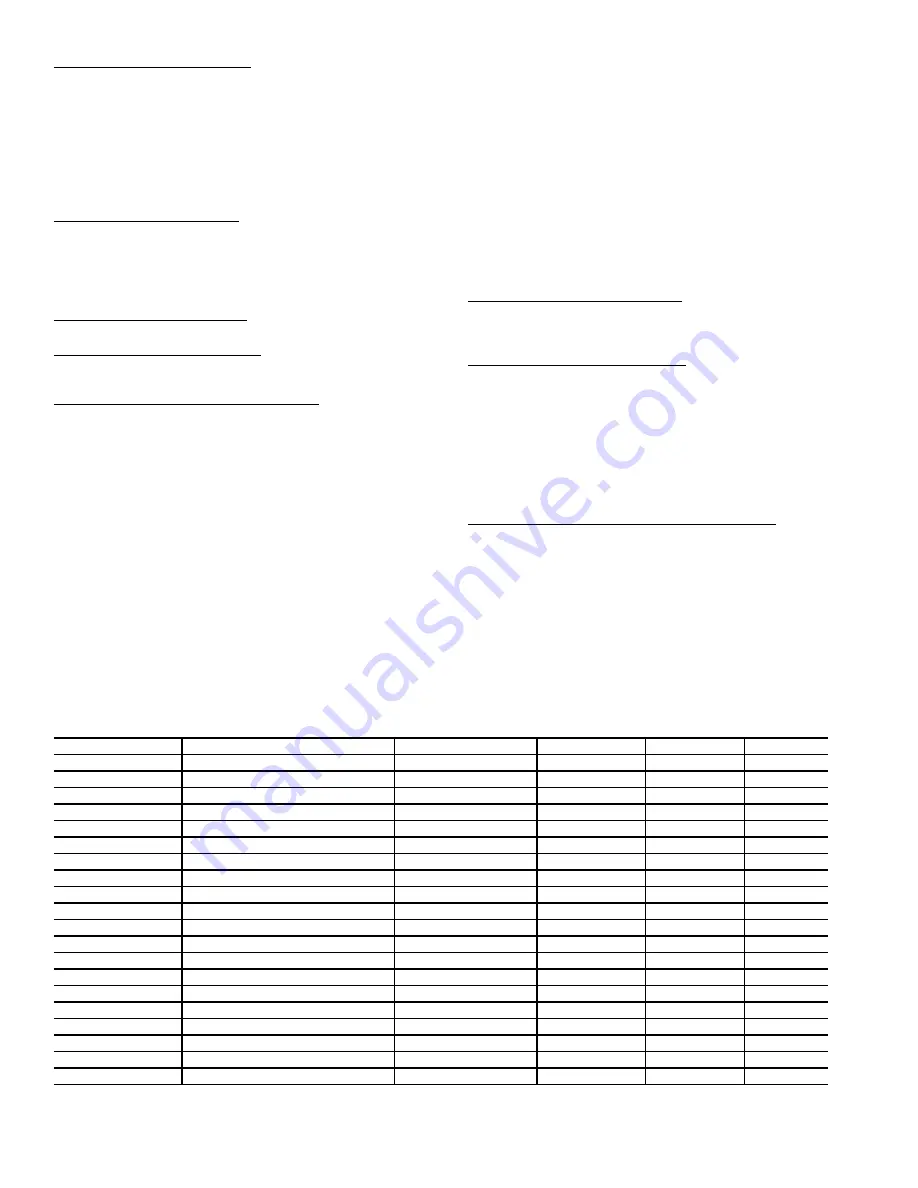
Table 75 — Static Pressure Control Configuration
*Some defaults are model number dependent.
ITEM
EXPANSION
RANGE
UNITS
CCN POINT
DEFAULT
SP
SUPPLY STATIC PRESS.CFG.
SP.CF
Static Pres. VFD Control?
0, 1
STATICFG
0*
SP.FN
Static Pres. Fan Control?
Yes/No
STATPFAN
Yes*
SP.S
Static Pressure Sensor
Enable/Disable
SPSENS
Disable*
SP.LO
Static Press. Low Range
–10 - 0
in. W.C.
SP_LOW
0
SP.HI
Static Press. High Range
0 - 10
in. W.C.
SP_HIGH
5
SP.SP
Static Pressure Setpoint
0 - 5
in. W.C.
SPSP
1.5
SP.MN
VFD Minimum Speed
0 - 100
%
STATPMIN
20
SP.MX
VFD Maximum Speed
0 - 100
%
STATPMAX
100
SP.FS
VFD Fire Speed Override
0 - 100
%
STATPFSO
100
SP.RS
Stat. Pres. Reset Config
0 - 4
SPRSTCFG
0
SP.RT
SP Reset Ratio (
/dF)
0 - 2.00
SPRRATIO
0.2
SP.LM
SP Reset Limit in iwc (
)
0 - 2.00
SPRLIMIT
0.75
SP.EC
SP Reset Econo.Position
0 - 100
%
ECONOSPR
5
S.PID
STAT.PRESS.PID CONFIGS
SP.TM
Static Press. PID Run Rate
1 - 200
sec
SPIDRATE
2
SP.P
Static Press. Prop. Gain
0 - 100
STATP_PG
20
SP.I
Static Press. Intg. Gain
0 - 50
STATP_IG
2
SP.D
Static Press. Derv. Gain
0 - 50
STATP_DG
0
SP.SG
Static Press. System Gain
0 - 50
STATP_SG
1.0
Содержание WEATHERMAKER 48/50AJ
Страница 103: ...103 Fig 15 Typical Main Control Box Wiring Schematic 48 50AJ AK AW AY Units cont a48 8355 ...
Страница 104: ...104 Fig 16 Typical Main Control Box Wiring Schematic 48 50A2 A3 A4 A5 Units a48 8355 ...
Страница 105: ...105 TO NEXT PAGE Fig 17 Typical Auxiliary Control Box Wiring Schematic A48 7294 ...
Страница 106: ...106 Fig 17 Typical Auxiliary Control Box Wiring Schematic cont a48 8356 ...
Страница 107: ...107 Fig 18 Typical 2 Stage Gas Heat Wiring Schematic Size 051 and 060 Units Shown a48 8357 ...
Страница 108: ...108 TO NEXT PAGE Fig 19 Typical Staged Gas Heat Wiring Schematic Size 051 and 060 Units Shown A48 7296 ...
Страница 109: ...109 Fig 19 Typical Staged Gas Heat Wiring Schematic Size 051 and 060 Units Shown cont A48 8358 ...
Страница 110: ...110 Fig 20 Typical Electric Heat Control Schematic 50 Series Size 051 and 060 Units Shown a50 8228 ...
Страница 111: ...111 TO NEXT PAGE Fig 21 Typical Power Schematic 48 50AJ AK AW AY051 and 060 Units Shown A48 7298 ...
Страница 112: ...112 FROM PREVIOUS PAGE Fig 21 Typical Power Schematic 48 50AJ AK AW AY051 and 060 Units Shown cont a48 8360 ...
Страница 113: ...113 Fig 22 Typical Power Schematic 48 50A2 A3 A4 A5060 Unit Shown ...
Страница 114: ...114 SW1 SW2 OR DEHUMIDIFY SWITCH Fig 23 Typical Controls Option Wiring Schematic a48 8361 ...
Страница 115: ...115 Fig 24 Typical Small Chassis Component Location Size 020 035 Units a48 8362 ...
Страница 116: ...116 Fig 25 Typical Large Chassis Component Locations Size 036 060 Units A48 7302 ...
Страница 169: ...169 APPENDIX C VFD INFORMATION cont Fig F Internal Enclosure Fan Replacement A48 7716 ...