3-4
Axxius 800 - Release 2.2
Electrical Installation and Cabling
Chassis Connections
Chassis Connections
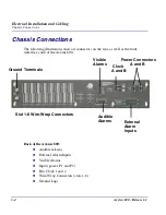
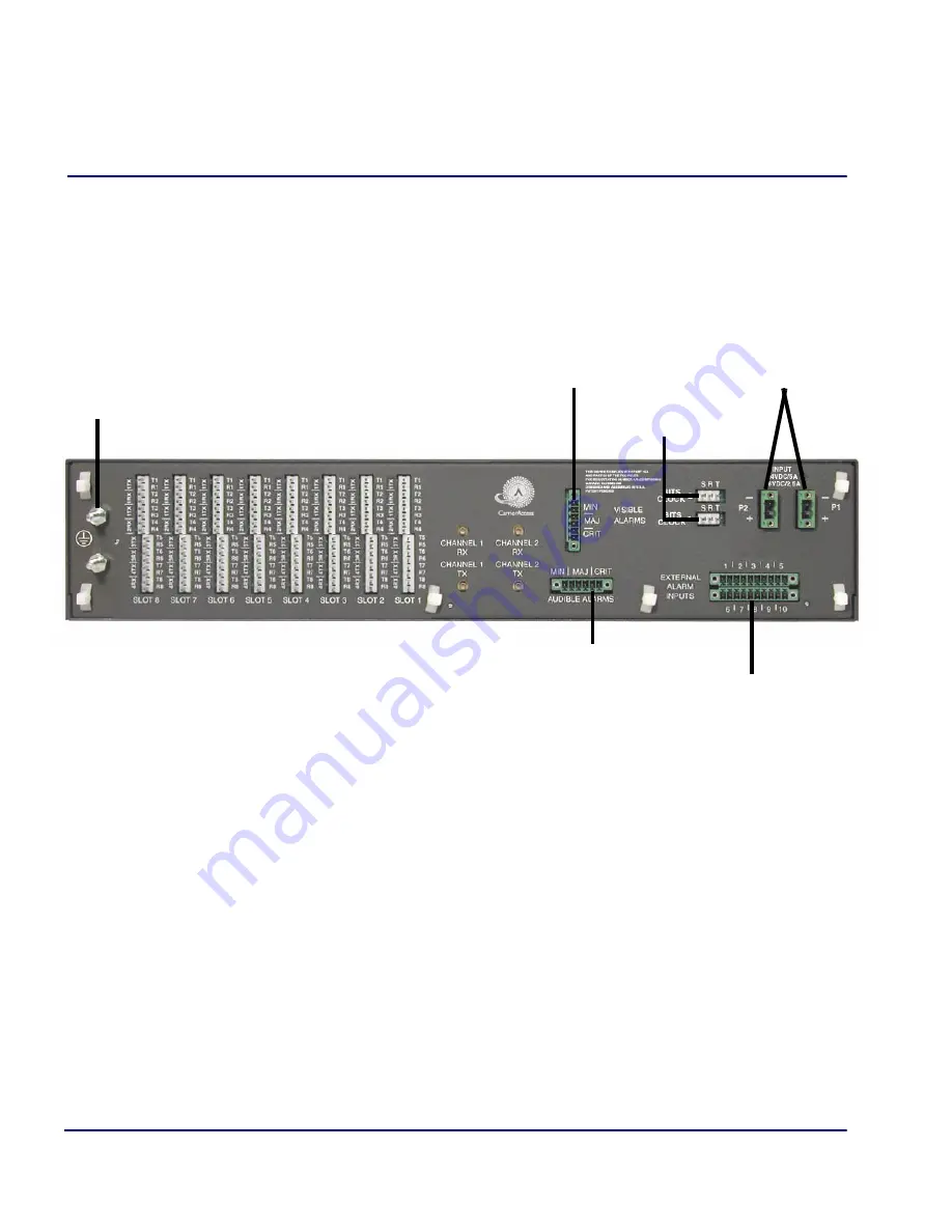
The following illustrations show all connectors on the rear, as well as the front
(interface card) of the Axxius 800.
Back of the Axxius 800:
l
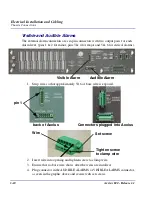
Audible Alarms
l
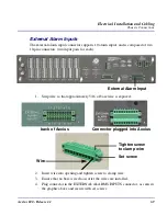
External Alarm Inputs
l
Visible Alarms
l
Input (power, P1 and P2)
l
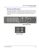
Bits Clock 1 and 2
l
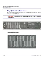
Wire-Wrap Connectors (slots 1-8)
l
Ground Lugs
Ground Terminals
Audible
Power Connectors
Visible
Clock
A and B
External
Alarm
Slot 1-8 Wire-Wrap Connectors
A and B
Alarms
Alarms
Inputs
Содержание Network Device Axxius 800
Страница 1: ...Axxius 800 USER MANUAL Part Number 770 0104 AG Product Release 2 2 May 2004 ...
Страница 32: ...xxxii Axxius 800 Release 2 2 Table of Contents ...
Страница 50: ...1 18 Axxius 800 Release 2 2 Base Platform ACO ...
Страница 101: ...CHAPTER CLI Commands In this Chapter n Command Line Interface Help n CLI Commands ...
Страница 392: ...8 8 Axxius 800 Release 2 2 FXO Voice Card Channel Associated Signaling CAS Conversions ...
Страница 430: ...12 8 Axxius 800 Release 2 2 Power Supply Installing Replacing a Power Supply ...
Страница 472: ...15 20 Axxius 800 Release 2 2 Terminal Server Router Card LEDs ...
Страница 500: ...18 12 Axxius 800 Release 2 2 Maintenance Hot Swap Service Card ...
Страница 511: ...APPENDIX Loopback Tests In this Appendix n Overview n DS1 Loopbacks n V 35 Loopbacks n V 35 V 54 Loop ...
Страница 532: ...C 22 Axxius 800 Release 2 2 Loopback Tests V 35 V 54 Loop ...
Страница 552: ...Glossary 20 Axxius 800 Release 2 2 Glossary ...

