14-8
Axxius 800 - Release 2.2
Quad T1 & Quad DS1/E1 Card
Jumper Settings
Jumper Settings
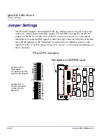
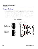
The P2 and P3 Jumpers are defaulted to RJ-48, which are the set of pins nearest the
connectors. In this position the DS1 signals (TX and RX) are routed to the RJ-48
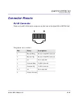
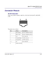
connectors on the face of the card, see RJ-48 Connector on page 14-9 for pinout
information. To route the DS1 signals to the wire-wrap connector at the rear of the unit,
move all the jumpers to the "backplane" position (the two rightmost pins for each
signal). See Slot (1-8) Wire-Wrap Connectors on page 3-12 for more information on
these connectors.
P2 and P3 Jumpers
Faceplate of T1 Card
P3
P2
3
24
1
22
3
24
1
BAC
KPLAN
E
BAC
KPL
AN
E
1
22
24
3
1
22
24
3
RJ
4
8
RJ
4
8
Jumper set to
RJ-48 connector
on the front of
the card
Jumper set to
Wire-Wrap
connectors on the
back of the chassis
Содержание Network Device Axxius 800
Страница 1: ...Axxius 800 USER MANUAL Part Number 770 0104 AG Product Release 2 2 May 2004 ...
Страница 32: ...xxxii Axxius 800 Release 2 2 Table of Contents ...
Страница 50: ...1 18 Axxius 800 Release 2 2 Base Platform ACO ...
Страница 101: ...CHAPTER CLI Commands In this Chapter n Command Line Interface Help n CLI Commands ...
Страница 392: ...8 8 Axxius 800 Release 2 2 FXO Voice Card Channel Associated Signaling CAS Conversions ...
Страница 430: ...12 8 Axxius 800 Release 2 2 Power Supply Installing Replacing a Power Supply ...
Страница 472: ...15 20 Axxius 800 Release 2 2 Terminal Server Router Card LEDs ...
Страница 500: ...18 12 Axxius 800 Release 2 2 Maintenance Hot Swap Service Card ...
Страница 511: ...APPENDIX Loopback Tests In this Appendix n Overview n DS1 Loopbacks n V 35 Loopbacks n V 35 V 54 Loop ...
Страница 532: ...C 22 Axxius 800 Release 2 2 Loopback Tests V 35 V 54 Loop ...
Страница 552: ...Glossary 20 Axxius 800 Release 2 2 Glossary ...

