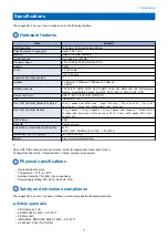
No.
Item
4
Printer interface port
5
Power connector
6
LEDs (2-digit soft progress display)
7
Service switch
8
Power switch
■ Exploded view of the imagePRESS Server components
1
2
3
4
5
6
7
8
9
10
11
13
14
15
16
17
19
18
12
20
Figure 3: Exploded view of components
No.
Item
1
Chassis cover
2
Printer interface board
3
CPU cooling assembly
4
4GB DIMMs (X 2)
5
CPU
6
Battery
7
Motherboard
8
SATA HDD data cable
9
10-pin power button cable
10
Storage device power cable
11
Storage device bracket
12
500GB SATA HDD
13
Chassis fan
14
Chassis fan guard
15
Power supply
16
Power switch
3. REPLACING PARTS
17
Содержание P 400
Страница 7: ...Introduction 1 Introduction 2 Specifications 7...
Страница 16: ...Using the imagePRESS Server 2 Using the imagePRESS Server 11...
Страница 21: ...REPLACING PARTS 3 Replacing parts 16...
Страница 51: ...INSTALLING SYSTEM SOFTWARE 4 Installing system software 46...
Страница 73: ...TROUBLESHOOTI NG 5 Troubleshooting 68...

