


9
9
9-79
9-79
Installation > USB Device Port-E4 > Installation Procedure
Installation > USB Device Port-E4 > Installation Procedure
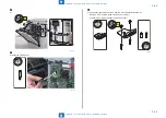
16)
Route the Power Supply Cable and secure the connector with the guide [A].
[A]
1x
17)
Remove the USB Mounting Plate (Removed USB Mounting Plate will be used in step
19).
• 2 Screws (Removed screws will be used in step 19.)
2x
F-9-190
F-9-191
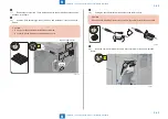
18)
Route the USB Cable, which was disconnected in step 12, as shown in the figure,
and connect it to the DP Board.
• 1 Screw (TP; M3x6)
• Harness Guide
1x
1x
TP Round End
M3×6
1x
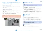
19)
Connect the DP USB Cable which is included in the package to the USB Mounting
Plate removed in step 17.
• 2 Bosses
• 2 Screws (Use the screws removed in step 17.)
Boss
Boss
2x
F-9-192
F-9-193
Содержание imageRUNNER ADVANCE C3325 Series
Страница 16: ...1 1 Product Overview Product Overview Product Lineup Features Specifications Parts Name ...
Страница 324: ...5 5 Adjustment Adjustment Pickup Feed System Document Exposure System Actions after Replacement ...
Страница 427: ...7 7 Error Jam Alarm Error Jam Alarm Overview Error Code Jam Code Alarm Code ...
Страница 552: ...8 8 Service Mode Service Mode Overview COPIER FEEDER SORTER BOARD ...
Страница 935: ... Service Tools General Circuit Diagram Backup Data Detail of HDD partition Soft counter specifications Removal Appendix ...
Страница 937: ...III III Appendix Service Tools Special Tools Appendix Service Tools Special Tools Solvents and Oils None ...


