


6
6
6-14
6-14
Troubleshooting■>■Startup■System■Failure■Diagnosis■>■Startup■Failure■Analysis■Policy
Troubleshooting■>■Startup■System■Failure■Diagnosis■>■Startup■Failure■Analysis■Policy
Startup■System■Failure■Diagnosis
The■viewpoint■of■this■Startup■System■Failure■Diagnosis
The■goal■of■the■startup■system■failure■diagnosis■is■to■be■able■to■solve■troubles■associated■
with■a■Control■Panel■display■failure■by■performing■the■following■steps.
It■is■assumed■that■the■users■have■already■learned■the■following■items:
•■ How■to■use■a■tester
•■ Roles■of■the■Low-voltage■Power■Supply■(3.3V,■12V)(Power■supply)
•■ How■to■back■up■data■(HDD■and■Flash■PCB)
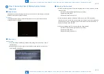
CAUTION:
AC■power■supply■is■always■supplied■to■the■Low-voltage■Power■Supply■PCB.■Pay■
attention■not■to■cause■short■circuit■when■accessing■the■PCB.
■
■
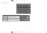
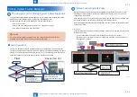
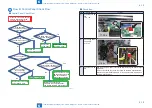
Useful■Operations
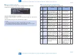
The■items■of■detailed■procedure■explanation■start■with■a■description■of■the■flow■diagram.■
The■items■and■procedures■checked■in■the■flow■diagram■are■described■separately■in■a■check■
item■table.■The■flow■diagram■contains■numbers■(e.g.■(1))■corresponding■to■the■check■items■
so■that■the■readers■can■grasp■the■relevant■parts■of■the■check■item■table.
Flow
Check item list
The location of each check item
can be referenced by the
corresponding number in the flow
diagram.
Has only
the backlight gone off?
(Can you hear the operation sound
of the Hard Key?)
Is 12V supplied to
C1005 of the Control Panel
CPU PCB?
Start
[Assumed failure location]
1. Control Panel CPU PCB
2. Main Controller PCB1
3. 12V Connector of the Control Panel
4. Control Panel Unit
No
Yes
Yes
[Assumed failure location]
1. Control Panel Unit
2. 12V Connector of the Control Panel
3. Main Controller PCB1
No
(1)
(2)
(3)
(2)
F-6-12
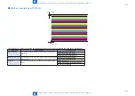
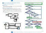
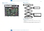
Startup■Failure■Analysis■Policy
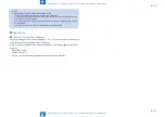
Startup■Failure■Analysis■Policy■describes■troubleshooting■related■to■"Execution■Flow■for■
Control■Panel■Startup■Failure"■for■the■Low-voltage■Power■Supply■(3.3V,■12V)■and■Low-
voltage■Power■Supply■PCB.
If■the■host■machine■does■not■start■successfully■even■when■its■Power■Switch■is■turned■ON,■
identify■the■location■of■the■failure■by■referencing■the■following■diagram.
Select■the■appropriate■failure■location■identification■procedure■based■on■the■display■status■
of■the■Control■Panel.
Preconditions
If■the■following■two■parts■are■not■operating■with■the■main■power■turned■ON,■it■is■likely■that■a■
failure■has■occurred.
•■ Control■Panel■Main■Power■LED■(Low-voltage■Power■Supply■3.3V■system)
•■ Rotation■noise■of■the■motor■at■warm-up■rotation■and■activation■of■the■Control■Panel■
Backlight■(12V■system)
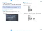
Not lit
Solid black
The logo is displayed
Only the bar is displayed
Power-On
Display of E-code
Countermeasures related to system software
- Reinstall the system.
- Replace the
SATA-Flash
.
Refer to the error code
correspondence table
for countermeasures
"NG" is displayed
as a result in the startup system
failure diagnosis
Yes
No
Flow A: Identifying the Cause Between
the Power Supply or the Main Controller
Flow C:
Execution Flow of
Startup System
Failure Diagnosis
Flow A: Identifying the Cause Between
the Power Supply or the Main Controller
Lit
EXXX-XXXX
F-6-13
Содержание imageRUNNER ADVANCE C3325 Series
Страница 16: ...1 1 Product Overview Product Overview Product Lineup Features Specifications Parts Name ...
Страница 324: ...5 5 Adjustment Adjustment Pickup Feed System Document Exposure System Actions after Replacement ...
Страница 427: ...7 7 Error Jam Alarm Error Jam Alarm Overview Error Code Jam Code Alarm Code ...
Страница 552: ...8 8 Service Mode Service Mode Overview COPIER FEEDER SORTER BOARD ...
Страница 935: ... Service Tools General Circuit Diagram Backup Data Detail of HDD partition Soft counter specifications Removal Appendix ...
Страница 937: ...III III Appendix Service Tools Special Tools Appendix Service Tools Special Tools Solvents and Oils None ...