2
2
2-67
2-67
Technical Explanation > Fixing System > Controls > Fixing Unit Life Detection
Technical Explanation > Fixing System > Controls > Fixing Unit Life Detection
■
Fixing Unit Detection
During warm-up rotation (at power-on/recovery from sleep mode/closing of the cover), the
Fixing Unit detection signal (FSR-CNCT-THX) is input to the DC Controller to detect the
Fixing Unit.
If the Fixing Unit is not detected, "Set the fixing assembly." is displayed on the Control Panel,
and operation stops.
■
Fixing Unit Life Detection
Purpose: To detect the life of the Fixing Unit in order to prevent fixing errors due to the Fixing
Unit having reached the end of life
This machine has a counter in the DC Controller to determine the life of the Fixing Unit.
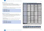
The life of the Fixing Unit is determined by the following 3 conditions:
1. Total drive time
Displayed when the sum of the total drive times reaches 2,150 hours.
2. Number of sheets fed
Displayed when 150,000 sheets have been fed
3. Total drive time + Number of sheets fed
Displayed when either of above conditions 1 or 2 is first detected
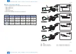
F-2-85
When these conditions reach certain limits "The fixing assembly needs to be replaced." is
displayed on the Control Panel status line.
Related Service Mode
:
(Lv.2) COPIER > OPTION > DSPLY-SW > FXMSG-SW : ON/OFF Fixing Unit
replacement message
0 to 1
0: OFF, 1: ON (default)
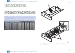
(Lv.2) COPIER> OPTION> FNC-SW> FXWRNLVL : To set the threshold value to
display the life of Fixing Film.
0 to 3
0: Warning is hidden. (default)
1: Warning is displayed when the counter for life judgment reaches the specified value.
(Driving time)
2: Warning is displayed when the counter for life judgment reaches the specified value.
(Number of sheets)
3: Warning is displayed when the counter for life judgment reaches the specified value.
(Both driving time and number of sheets)
The life of the Fixing Unit is detected when FXMSG-SW and FXWRNLVL is 1.
As the default value of FXWRNLVL is 0, the life is not detected at factory default.
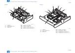
F-2-86
Содержание imageRUNNER ADVANCE C3325 Series
Страница 16: ...1 1 Product Overview Product Overview Product Lineup Features Specifications Parts Name ...
Страница 324: ...5 5 Adjustment Adjustment Pickup Feed System Document Exposure System Actions after Replacement ...
Страница 427: ...7 7 Error Jam Alarm Error Jam Alarm Overview Error Code Jam Code Alarm Code ...
Страница 552: ...8 8 Service Mode Service Mode Overview COPIER FEEDER SORTER BOARD ...
Страница 935: ... Service Tools General Circuit Diagram Backup Data Detail of HDD partition Soft counter specifications Removal Appendix ...
Страница 937: ...III III Appendix Service Tools Special Tools Appendix Service Tools Special Tools Solvents and Oils None ...


