9
9
9-44
9-44
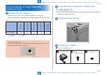
Installation > Copy Card Reader-F1/Copy Card Reader Attachment Kit-B4 > Installation Procedure > Removing the Covers
Installation > Copy Card Reader-F1/Copy Card Reader Attachment Kit-B4 > Installation Procedure > Removing the Covers
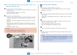
■
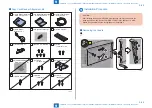
Copy Card Reader Attachment-B4
[1] Card Reader Mounting
Plate (front) Unit X 1
[2] Card Reader Mounting
Plate (rear) Unit X 1
[3] Card reader External
Relay Cable X 1
[4] Card Reader
Relay Unit X 1
[5] Connector Cover X 1
[10] Card Reader Mounting
Plate (lower) Unit X 1
[6] Cord Guide X 2
[13] PCB Spacer X 1
[12] Connector Cover X 1
[8] Screw (TP; M3x6) X 5
[9] Screw
(TP; M3x12) X 2
[14] Screw
(TP; M4x12) X 2
[15] Screw
(Binding; M4x6) X 4
[11] Screw
(W Sams; M3x14) X 2
[7] Wire Saddle X 1
F-9-94
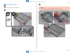
Installation Procedure
CAUTION:
After installing the Copy Card Reader, enter the card number to be used in the
following service mode (Level 1): COPIER > FUNCTION > INSTALL > CARD.
Otherwise, the card will not be recognized even if inserting it.
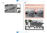
■
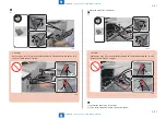
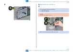
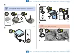
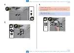
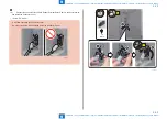
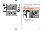
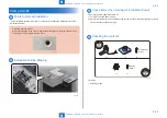
Removing the Covers
1)
2x
F-9-95
Содержание imageRUNNER ADVANCE C3325 Series
Страница 16: ...1 1 Product Overview Product Overview Product Lineup Features Specifications Parts Name ...
Страница 324: ...5 5 Adjustment Adjustment Pickup Feed System Document Exposure System Actions after Replacement ...
Страница 427: ...7 7 Error Jam Alarm Error Jam Alarm Overview Error Code Jam Code Alarm Code ...
Страница 552: ...8 8 Service Mode Service Mode Overview COPIER FEEDER SORTER BOARD ...
Страница 935: ... Service Tools General Circuit Diagram Backup Data Detail of HDD partition Soft counter specifications Removal Appendix ...
Страница 937: ...III III Appendix Service Tools Special Tools Appendix Service Tools Special Tools Solvents and Oils None ...

