


9
9
9-75
9-75
Installation > USB Device Port-E4 > Installation Procedure
Installation > USB Device Port-E4 > Installation Procedure
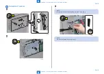
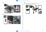
5) Install the DP Base Cover to the DP Base.
• 2 Bosses
• 4 Hooks
NOTE:
Align the 2 hooks [A] and the bosses (in the DP Base Cover) with the corresponding
holes for the hooks and long holes for the bosses (in the DP Base), and push the DP
base in to the DP Base Cover. Installation becomes difficult if the bosses and their
positioning holes are aligned first.
Hook [A]
Hook
Boss
Hook
Hook [A]
F-9-179
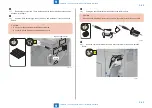
6) Install the DP Mounting Plate to the DP Lower Cover Unit.
• 2 Bosses
• 4 Screws (Binding; M4x6)
4x
Boss
Boss
Binding
M4x6
F-9-180
Содержание imageRUNNER ADVANCE C3325 Series
Страница 16: ...1 1 Product Overview Product Overview Product Lineup Features Specifications Parts Name ...
Страница 324: ...5 5 Adjustment Adjustment Pickup Feed System Document Exposure System Actions after Replacement ...
Страница 427: ...7 7 Error Jam Alarm Error Jam Alarm Overview Error Code Jam Code Alarm Code ...
Страница 552: ...8 8 Service Mode Service Mode Overview COPIER FEEDER SORTER BOARD ...
Страница 935: ... Service Tools General Circuit Diagram Backup Data Detail of HDD partition Soft counter specifications Removal Appendix ...
Страница 937: ...III III Appendix Service Tools Special Tools Appendix Service Tools Special Tools Solvents and Oils None ...