


6
6
6-21
6-21
Troubleshooting■>■Controller■Self■Diagnosis■>■Controller■Self■Diagnosis■>■Basic■Flowchart
Troubleshooting■>■Controller■Self■Diagnosis■>■Controller■Self■Diagnosis■>■Basic■Flowchart
■
■
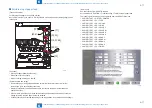
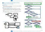
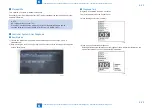
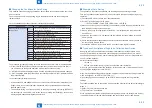
Layout■Drawing
■
●
Layout■Drawing■of■PCBs■Subject■to■Diagnosis
HDD
Main Controller PCB
TPM PCB
Flash PCB
USB I/F
F-6-21
■
■
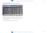
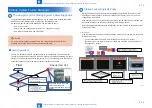
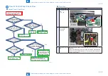
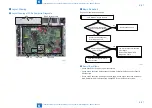
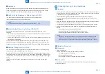
Basic■Flowchart
Check■all■of■the■items■shown■below.
Yes
Yes
No
No
Turn ON the main power switch.
Does the Power supply LED
on the Control Panel light up?
Execute basic check.
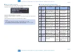
Execute Controller System
Error Diagnosis Tool.
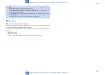
Take an action appropriate for
the error Code.
Is display a judgment result
of [OK] or [NG]?
The error locations are identified
according to
the Controller System Error
Diagnosis Table.
■
●
Basic■Check■Items
•■ Check■if■the■Power■Supply■Plug■is■disconnected.
•■ Check■if■the■Connection■Cable■between■the■Main■Controller■PCB■and■Control■Panel■is■
disconnected.
•■ Check■if■the■Connection■An■All-night■Power■Supply.■Check■if■the■Connection■Cable■from■
Main■Controller■PCB■is■disconnected.■Change■AC■Driver■PCB■if■not■recovered.
F-6-22
Содержание imageRUNNER ADVANCE C3325 Series
Страница 16: ...1 1 Product Overview Product Overview Product Lineup Features Specifications Parts Name ...
Страница 324: ...5 5 Adjustment Adjustment Pickup Feed System Document Exposure System Actions after Replacement ...
Страница 427: ...7 7 Error Jam Alarm Error Jam Alarm Overview Error Code Jam Code Alarm Code ...
Страница 552: ...8 8 Service Mode Service Mode Overview COPIER FEEDER SORTER BOARD ...
Страница 935: ... Service Tools General Circuit Diagram Backup Data Detail of HDD partition Soft counter specifications Removal Appendix ...
Страница 937: ...III III Appendix Service Tools Special Tools Appendix Service Tools Special Tools Solvents and Oils None ...