


3 -57
3 -59
3 -67
3 -67
3
1
1
2
2
3
4 -10
7.1
User report output functions
7.1.2 Service report output functions
WIRING DIAGRAM
6.1 Wiring Diagram
8.2 Connector Name and Signal Descriptions
Chapter 4: Appendix
INSTALLATION
Setting Up
1.2 Checking Operations
2. USER DATA FLOW
2.1 USER DATA FLOW (by Operation Panel)
2.2 USER DATA FLOW (by
Desktop Manager)
2.3 SPECIAL MODE FLOW (by Operation Panel)
3. MAKER CODE
INDEX
VII
Содержание C5000 - MultiPASS Color Inkjet Printer
Страница 1: ...MultiPASS C5000 SERVICE MANUAL Canon ...
Страница 5: ...REVISION I CONTENT 0 I Original ...
Страница 26: ...Chapter 7 General Description 3 1 External View Front View Figure 1 3 External View 1 l 11 ...
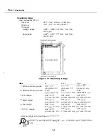
Страница 27: ...Part 1 Facsimile Rear View Inside the Printer Cover Figure 1 4 External View 2 1 12 ...
Страница 28: ...Part 7 Facsimile 3 2 Operation Panel The Operation Panel Document feed lever 0 0 0 0 1 14 ...
Страница 34: ...Part 1 Facsimile ...
Страница 36: ...Part 7 Facsimile r w Units mm r 0 4 0 0 Figure l 13 Dimensions l 22 ...
Страница 57: ...Chapter 1 General Description 5 3 3 Print assembly BJ Cartridge _ Figure l 20 Print Assembly Precautions l 43 ...
Страница 65: ...Chapter 1 General Description Waste Ink absorber Figure 1 23 Waste Ink Absorber 1 51 ...
Страница 92: ...Part 7 Facsimile Figure 2 18 Printing Signals HQ Mode 2 24 ...
Страница 93: ...Chapter 2 Technical Refereno 6 1 Component Block Diagram Figure 2 19 Block Diagram 2 25 ...
Страница 150: ...Part 1 Facsimile Figure 3 28 Print Pattern Sample 3 48 ...
Страница 164: ... Part 1 Facsimile a 2 System dump list a STSrn DlYP LIST t t tf t Figure 3 35 System Dump List l 2 3 62 ...
Страница 184: ...Part 1 Facsimile U Vertical alignment Correction l l l l 3 7 ...
Страница 194: ...Part 2 Printer 3 1 Interface Connector 81 DIRECTIONAL PARALLEL PORT Figure 1 4 Interface Connector l 10 ...
Страница 212: ...Chapter 3 Maintenance Service See Part 1 Facsimile Chapter 3 Maintenance Service for details REFERENCE 3 1 ...