
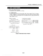


1: Facsimile
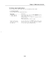
c) Line signal reception test
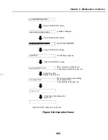
The line detect test menu is selected by pressing the 9 button from the faculty test menu.
This test checks the operation of the NCU signal sensor and frequency counter. In Menu
1, the CI, status can be detected and in Menu 2 the frequency can be detected at changing
detection levels. In this way, you can check if the NCU board is correctly detecting
signals.
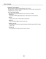
c-l) Test Menu
Test Menu 1 is selected by pressing the button from the Line Detect menu. When CI,
is detected from the modular jack, the display changes from OFF to ON and the received
frequency is displayed.
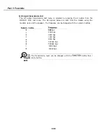
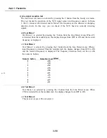
c-2)
Test Menu 2
Test Menu 2 is selected by pressing the 2 button from the Line Detect menu. When a
tonal frequency is detected from the modular jack, the display changes from OFF to ON
and the received frequency is displayed. The frequency detection level can be set with
the numeric buttons.
Numeric button
Detection level
_
0
-26
1
-30
2
-32
3
-35
4
-38
5
-41
6
8
-47
9
-51
c-3) Test Menu 3
Test Menu 3 is selected by pressing the 3 button from the Line Detect menu. When
CNG is detected from the modular jack, the display changes from OFF to ON.
c-4)
Test Menu 4
This item is not used. Do not select it
3-56
Содержание C5000 - MultiPASS Color Inkjet Printer
Страница 1: ...MultiPASS C5000 SERVICE MANUAL Canon ...
Страница 5: ...REVISION I CONTENT 0 I Original ...
Страница 26: ...Chapter 7 General Description 3 1 External View Front View Figure 1 3 External View 1 l 11 ...
Страница 27: ...Part 1 Facsimile Rear View Inside the Printer Cover Figure 1 4 External View 2 1 12 ...
Страница 28: ...Part 7 Facsimile 3 2 Operation Panel The Operation Panel Document feed lever 0 0 0 0 1 14 ...
Страница 34: ...Part 1 Facsimile ...
Страница 36: ...Part 7 Facsimile r w Units mm r 0 4 0 0 Figure l 13 Dimensions l 22 ...
Страница 57: ...Chapter 1 General Description 5 3 3 Print assembly BJ Cartridge _ Figure l 20 Print Assembly Precautions l 43 ...
Страница 65: ...Chapter 1 General Description Waste Ink absorber Figure 1 23 Waste Ink Absorber 1 51 ...
Страница 92: ...Part 7 Facsimile Figure 2 18 Printing Signals HQ Mode 2 24 ...
Страница 93: ...Chapter 2 Technical Refereno 6 1 Component Block Diagram Figure 2 19 Block Diagram 2 25 ...
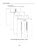
Страница 150: ...Part 1 Facsimile Figure 3 28 Print Pattern Sample 3 48 ...
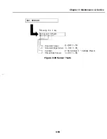
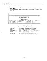
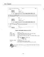
Страница 164: ... Part 1 Facsimile a 2 System dump list a STSrn DlYP LIST t t tf t Figure 3 35 System Dump List l 2 3 62 ...
Страница 184: ...Part 1 Facsimile U Vertical alignment Correction l l l l 3 7 ...
Страница 194: ...Part 2 Printer 3 1 Interface Connector 81 DIRECTIONAL PARALLEL PORT Figure 1 4 Interface Connector l 10 ...
Страница 212: ...Chapter 3 Maintenance Service See Part 1 Facsimile Chapter 3 Maintenance Service for details REFERENCE 3 1 ...