

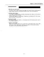


Chapter 1: General Description
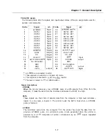
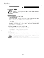
Connector
signals
The following table lists the signals and input/output status of the pin assignments used for
parallel communication
Pin No
1
2
3
4
5
6
7
8
9
10
11
12
13
14
15
16
17
18
Signal
-STROBE
DATA1
DATA2
DATA3
DATA4
DATA5
DATA6
DATA7
DATA8
BUSY
P.E.
SELECT
AUTO FEED
No Connection
GND
GND
P
output
In No.
19
20
21
22
23
24
25
26
28
29
30
31
32
33
34
35
36
Signal
DATA1 -RET
DATA2 -RET
DATA3 -RET
DATA4 -RET
DATA5 -RET
DATA6 -RET
DATA1 -RET
DATA8 -RET
-RET
BUSY -RET
P.E. -RET
-ERROR
GND
No Connection
IN*2
All
are connected to GND
These signals are valid only in Epson LQ mode.
This signal is connected to
via
resistor
The level is raised to
at 390R resistor.
Input
output
output
Signal descriptions
-STROBE
When
the printer receives a low -STROBE pulse of width greater than
from the
computer, it reads the data from the interface and makes the BUSY line high.
DATA
These signals are the 8 bits of parallel data from the computer. A high level indicates
logical 1; a low level, a logical 0. The printer reads the DATA lines when a -STROBE
pulse is received.
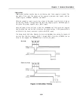
-ACKNLG
The ACKNLG pulse tells the computer
the printer has read the data from
previous -STROBE pulse. An
pulse is also generated when the printer is
powered on, or at
completion of printer initialization by an
signal requested
from the computer.
1 - 7
Содержание C5000 - MultiPASS Color Inkjet Printer
Страница 1: ...MultiPASS C5000 SERVICE MANUAL Canon ...
Страница 5: ...REVISION I CONTENT 0 I Original ...
Страница 26: ...Chapter 7 General Description 3 1 External View Front View Figure 1 3 External View 1 l 11 ...
Страница 27: ...Part 1 Facsimile Rear View Inside the Printer Cover Figure 1 4 External View 2 1 12 ...
Страница 28: ...Part 7 Facsimile 3 2 Operation Panel The Operation Panel Document feed lever 0 0 0 0 1 14 ...
Страница 34: ...Part 1 Facsimile ...
Страница 36: ...Part 7 Facsimile r w Units mm r 0 4 0 0 Figure l 13 Dimensions l 22 ...
Страница 57: ...Chapter 1 General Description 5 3 3 Print assembly BJ Cartridge _ Figure l 20 Print Assembly Precautions l 43 ...
Страница 65: ...Chapter 1 General Description Waste Ink absorber Figure 1 23 Waste Ink Absorber 1 51 ...
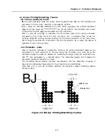
Страница 92: ...Part 7 Facsimile Figure 2 18 Printing Signals HQ Mode 2 24 ...
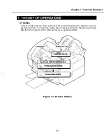
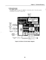
Страница 93: ...Chapter 2 Technical Refereno 6 1 Component Block Diagram Figure 2 19 Block Diagram 2 25 ...
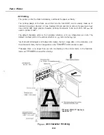
Страница 150: ...Part 1 Facsimile Figure 3 28 Print Pattern Sample 3 48 ...
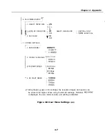
Страница 164: ... Part 1 Facsimile a 2 System dump list a STSrn DlYP LIST t t tf t Figure 3 35 System Dump List l 2 3 62 ...
Страница 184: ...Part 1 Facsimile U Vertical alignment Correction l l l l 3 7 ...
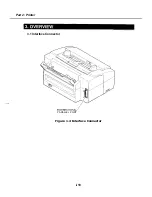
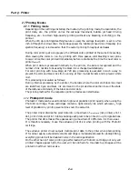
Страница 194: ...Part 2 Printer 3 1 Interface Connector 81 DIRECTIONAL PARALLEL PORT Figure 1 4 Interface Connector l 10 ...
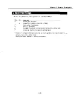
Страница 212: ...Chapter 3 Maintenance Service See Part 1 Facsimile Chapter 3 Maintenance Service for details REFERENCE 3 1 ...