


Chapter Genera/ Description
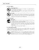
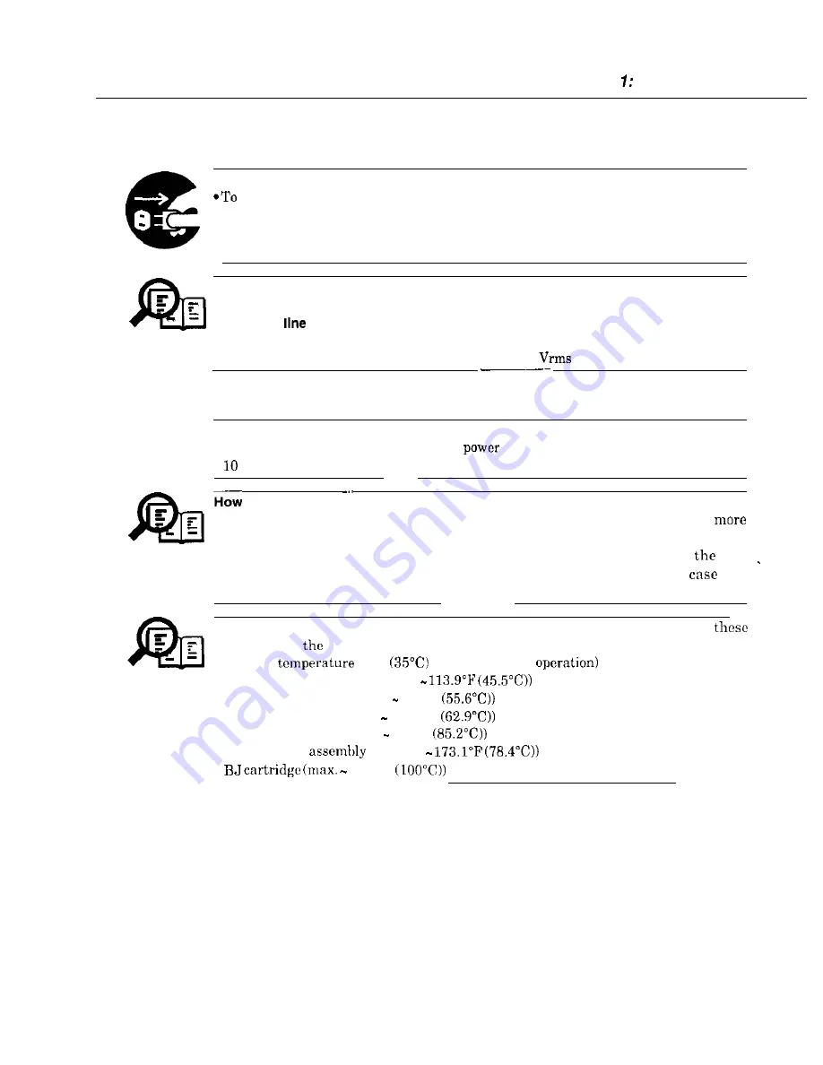
5.1.1 Electrical shock
Electrical shock hazard
I
prevent electrical shock, be sure to disconnect the power cord and modular jack
before disassembly.
*Remove grounding wrist straps before servicing this unit while the FAX’s power is
on. Otherwise, electrical shock may occur.
bower supply unit
When power is supplied to this unit, 120 VAC will be supplied to the primary side.
Telephone
NOTE
If a telephone line is connected to this unit, 48 VDC will be supplied by this line.
When a call signal is received, a voltage of 90 VAC
will be supplied.
5.1.2 High-temperature parts
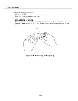
A
High-temperature warning
To prevent skin burns, disconnect the
cord and let this unit stand for at least
minutes to allow hot parts to cool.
to treat burns
Heat of about 122°F or more causes burns. Also, the longer the contact, the
severe the burn.
NOTE
When treating a burn, the first minute after receiving the burn is
most
important. Cool the burn immediately with cold running water. In
of a
serious burn, seek medical attention immediately.
The parts which get hot during operation are indicated. For the location of
parts, refer to
figures.
(Ambient
95°F
continuous copy
NOTE
Document
feed motor (approx.
Paper feed motor (approx. 132°F
Carriage motor (approx. 145.2-F
Power supply unit (Max. 185°F
PCNT board
(approx.
212°F
l-25
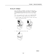
Содержание C5000 - MultiPASS Color Inkjet Printer
Страница 1: ...MultiPASS C5000 SERVICE MANUAL Canon ...
Страница 5: ...REVISION I CONTENT 0 I Original ...
Страница 26: ...Chapter 7 General Description 3 1 External View Front View Figure 1 3 External View 1 l 11 ...
Страница 27: ...Part 1 Facsimile Rear View Inside the Printer Cover Figure 1 4 External View 2 1 12 ...
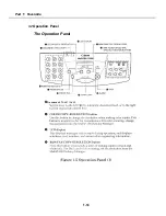
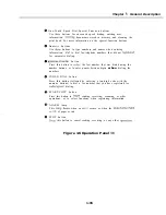
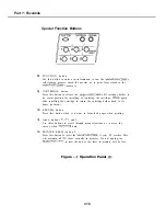
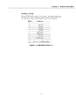
Страница 28: ...Part 7 Facsimile 3 2 Operation Panel The Operation Panel Document feed lever 0 0 0 0 1 14 ...
Страница 34: ...Part 1 Facsimile ...
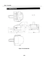
Страница 36: ...Part 7 Facsimile r w Units mm r 0 4 0 0 Figure l 13 Dimensions l 22 ...
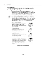
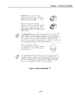
Страница 57: ...Chapter 1 General Description 5 3 3 Print assembly BJ Cartridge _ Figure l 20 Print Assembly Precautions l 43 ...
Страница 65: ...Chapter 1 General Description Waste Ink absorber Figure 1 23 Waste Ink Absorber 1 51 ...
Страница 92: ...Part 7 Facsimile Figure 2 18 Printing Signals HQ Mode 2 24 ...
Страница 93: ...Chapter 2 Technical Refereno 6 1 Component Block Diagram Figure 2 19 Block Diagram 2 25 ...
Страница 150: ...Part 1 Facsimile Figure 3 28 Print Pattern Sample 3 48 ...
Страница 164: ... Part 1 Facsimile a 2 System dump list a STSrn DlYP LIST t t tf t Figure 3 35 System Dump List l 2 3 62 ...
Страница 184: ...Part 1 Facsimile U Vertical alignment Correction l l l l 3 7 ...
Страница 194: ...Part 2 Printer 3 1 Interface Connector 81 DIRECTIONAL PARALLEL PORT Figure 1 4 Interface Connector l 10 ...
Страница 212: ...Chapter 3 Maintenance Service See Part 1 Facsimile Chapter 3 Maintenance Service for details REFERENCE 3 1 ...