


Part 1: Facsimile
3.3
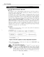
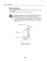
Head Gap Adjustment
a) When adjustment is required
If
carriage guide frame fastened to the printer frame is repositioned, the
gap
must be adjusted.
The screws are painted red to prevent them from being loosened.
Only the head gap between the
cartridge’s head face and platen needs to be
adjusted (to approximately 1.2 mm) to ensure optimum print quality.
This adjustment is done by moving the carriage guide frame forward back.
NOTE
The head gap differs depending on the position of the paper thickness lever.
To adjust the head gap,
the paper thickness
to the
(for plain
paper printing with a black
cartridge) and set the head gap to
approximately 1.2 mm.
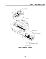
Carriage
Frame
.
Head Gap
Figure 3-8
3-10
Содержание C5000 - MultiPASS Color Inkjet Printer
Страница 1: ...MultiPASS C5000 SERVICE MANUAL Canon ...
Страница 5: ...REVISION I CONTENT 0 I Original ...
Страница 26: ...Chapter 7 General Description 3 1 External View Front View Figure 1 3 External View 1 l 11 ...
Страница 27: ...Part 1 Facsimile Rear View Inside the Printer Cover Figure 1 4 External View 2 1 12 ...
Страница 28: ...Part 7 Facsimile 3 2 Operation Panel The Operation Panel Document feed lever 0 0 0 0 1 14 ...
Страница 34: ...Part 1 Facsimile ...
Страница 36: ...Part 7 Facsimile r w Units mm r 0 4 0 0 Figure l 13 Dimensions l 22 ...
Страница 57: ...Chapter 1 General Description 5 3 3 Print assembly BJ Cartridge _ Figure l 20 Print Assembly Precautions l 43 ...
Страница 65: ...Chapter 1 General Description Waste Ink absorber Figure 1 23 Waste Ink Absorber 1 51 ...
Страница 92: ...Part 7 Facsimile Figure 2 18 Printing Signals HQ Mode 2 24 ...
Страница 93: ...Chapter 2 Technical Refereno 6 1 Component Block Diagram Figure 2 19 Block Diagram 2 25 ...
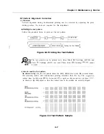
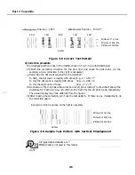
Страница 150: ...Part 1 Facsimile Figure 3 28 Print Pattern Sample 3 48 ...
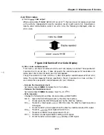
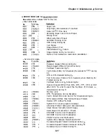
Страница 164: ... Part 1 Facsimile a 2 System dump list a STSrn DlYP LIST t t tf t Figure 3 35 System Dump List l 2 3 62 ...
Страница 184: ...Part 1 Facsimile U Vertical alignment Correction l l l l 3 7 ...
Страница 194: ...Part 2 Printer 3 1 Interface Connector 81 DIRECTIONAL PARALLEL PORT Figure 1 4 Interface Connector l 10 ...
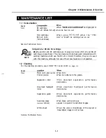
Страница 212: ...Chapter 3 Maintenance Service See Part 1 Facsimile Chapter 3 Maintenance Service for details REFERENCE 3 1 ...