


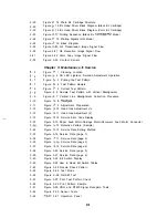


Part 1: Facsimile
Page
1- 6
1 -11
1 -12
1 -14
1 -15
1 -16
1 -17
1 -16
1 -19
1 -20
1 -21
-22
1 -23
-24
1 -38
1 -39
1 -40
1 -41
-43
1 -46
-47
1 -51
-53
1
2
3
6
6
9
2 -11
2 - 1 3
2 -13
2 -16
2 -19
2 -19
2 -20
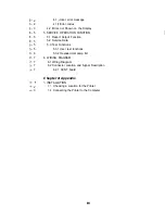
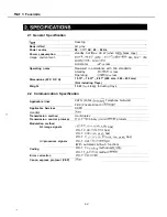
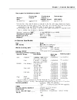
Chapter General Description
Figure 1- 1
Scanning Range
F i g u r e 2
Printing Range
F i g u r e 3 External View
F i g u r e 4
External View (2)
F i g u r e 5 Operation Panel
F i g u r e 6 Operation Panel (2)
F i g u r e 7 Operation Panel (3)
F i g u r e 6 Operation Panel (4)
F i g u r e 9 Consumables
Figure
Consumables (2)
Figure
Print Media (1)
Figure l-12 Print Media (2)
Figure l-13
Dimensions
Figure 14
Personnel Hazards
Figure l-15
Personnel Hazards (2)
Figure l-16 Unpacking the BJ Cartridge
Figure
Ink Path Cartridge
Figure
Removing Cartridge Cap
Figure l-19 Ink Outlet
Figure l-20 Print Assembly Precautions
Figure
Opening the Upper Cover
Figure l-22 Memory IC and Backed up Devices
Figure l-23 Waste Ink Absorber
Figure 1-24 All Clear
Chapter 2: Technical Reference
F i g u r e
Mechanical Layout
Figure 2
Electrical System Layout
Figure 3
Document Feed Section
Figure 4 Paper Feed Section
Figure 5 Paper Feed Motor Drive Switching
Figure 6
Paper Separation Mechanism
Figure 7
Printer Section
F i g u r e
Purge Unit
Figure 9
Pump Operation State Detection
Figure
Ink Empty Detection
Figure 11
Nozzle Arrangement
Figure 12
Black BJ Cartridge Structure
Figure 13 Color BJ Cartridge Structure
X
Содержание C5000 - MultiPASS Color Inkjet Printer
Страница 1: ...MultiPASS C5000 SERVICE MANUAL Canon ...
Страница 5: ...REVISION I CONTENT 0 I Original ...
Страница 26: ...Chapter 7 General Description 3 1 External View Front View Figure 1 3 External View 1 l 11 ...
Страница 27: ...Part 1 Facsimile Rear View Inside the Printer Cover Figure 1 4 External View 2 1 12 ...
Страница 28: ...Part 7 Facsimile 3 2 Operation Panel The Operation Panel Document feed lever 0 0 0 0 1 14 ...
Страница 34: ...Part 1 Facsimile ...
Страница 36: ...Part 7 Facsimile r w Units mm r 0 4 0 0 Figure l 13 Dimensions l 22 ...
Страница 57: ...Chapter 1 General Description 5 3 3 Print assembly BJ Cartridge _ Figure l 20 Print Assembly Precautions l 43 ...
Страница 65: ...Chapter 1 General Description Waste Ink absorber Figure 1 23 Waste Ink Absorber 1 51 ...
Страница 92: ...Part 7 Facsimile Figure 2 18 Printing Signals HQ Mode 2 24 ...
Страница 93: ...Chapter 2 Technical Refereno 6 1 Component Block Diagram Figure 2 19 Block Diagram 2 25 ...
Страница 150: ...Part 1 Facsimile Figure 3 28 Print Pattern Sample 3 48 ...
Страница 164: ... Part 1 Facsimile a 2 System dump list a STSrn DlYP LIST t t tf t Figure 3 35 System Dump List l 2 3 62 ...
Страница 184: ...Part 1 Facsimile U Vertical alignment Correction l l l l 3 7 ...
Страница 194: ...Part 2 Printer 3 1 Interface Connector 81 DIRECTIONAL PARALLEL PORT Figure 1 4 Interface Connector l 10 ...
Страница 212: ...Chapter 3 Maintenance Service See Part 1 Facsimile Chapter 3 Maintenance Service for details REFERENCE 3 1 ...