


Chapter 2: Technical Reference
Reading color documents
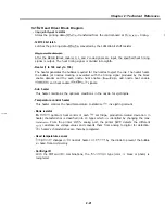
When scanning a line of color
LED’s are sequentially lit: first Red, then
Green, then Blue. The corresponding image data
line are then read and stored to
memory. The Red, Green and Blue LED’s are mounted on the white LED board at the right
side of the contact sensor. The light emitted from
LED’s passes through the optical
guide, where it is reflected, gathered.
at the document.
During color copying, the SCNT board’s Color Image Processing IC UC
the
data
in memory for each
color generate print image data for the colors Cyan,
Magenta, Yellow, and Black CMYK data Generation of CMYK data is independent
from the reading contact sensor data.
data generation is slower than the
reading process, reading is halted until
data generation is completed.
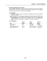
When using the unit as a color scanner,
Red, Green and Blue data which were scanned
and stored to memory are converted to
data and sent to the PC via the Centronics
interface.
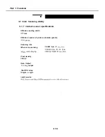
8.1.3 Reading black white documents
When scanning black and white
Green and Blue LED’s are lit
sequentially for
the duration used
color
providing illumination equivalent
to the
duration of white light.
G 8.
Figure 2-23 Contact Sensor
2-35
Содержание C5000 - MultiPASS Color Inkjet Printer
Страница 1: ...MultiPASS C5000 SERVICE MANUAL Canon ...
Страница 5: ...REVISION I CONTENT 0 I Original ...
Страница 26: ...Chapter 7 General Description 3 1 External View Front View Figure 1 3 External View 1 l 11 ...
Страница 27: ...Part 1 Facsimile Rear View Inside the Printer Cover Figure 1 4 External View 2 1 12 ...
Страница 28: ...Part 7 Facsimile 3 2 Operation Panel The Operation Panel Document feed lever 0 0 0 0 1 14 ...
Страница 34: ...Part 1 Facsimile ...
Страница 36: ...Part 7 Facsimile r w Units mm r 0 4 0 0 Figure l 13 Dimensions l 22 ...
Страница 57: ...Chapter 1 General Description 5 3 3 Print assembly BJ Cartridge _ Figure l 20 Print Assembly Precautions l 43 ...
Страница 65: ...Chapter 1 General Description Waste Ink absorber Figure 1 23 Waste Ink Absorber 1 51 ...
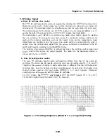
Страница 92: ...Part 7 Facsimile Figure 2 18 Printing Signals HQ Mode 2 24 ...
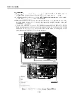
Страница 93: ...Chapter 2 Technical Refereno 6 1 Component Block Diagram Figure 2 19 Block Diagram 2 25 ...
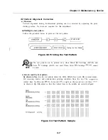
Страница 150: ...Part 1 Facsimile Figure 3 28 Print Pattern Sample 3 48 ...
Страница 164: ... Part 1 Facsimile a 2 System dump list a STSrn DlYP LIST t t tf t Figure 3 35 System Dump List l 2 3 62 ...
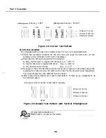
Страница 184: ...Part 1 Facsimile U Vertical alignment Correction l l l l 3 7 ...
Страница 194: ...Part 2 Printer 3 1 Interface Connector 81 DIRECTIONAL PARALLEL PORT Figure 1 4 Interface Connector l 10 ...
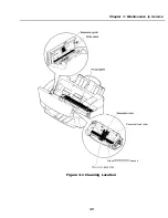
Страница 212: ...Chapter 3 Maintenance Service See Part 1 Facsimile Chapter 3 Maintenance Service for details REFERENCE 3 1 ...