


Part 1: Facsimile
a) General precautions
Head gap
The head gap is the distance between the
head and the platen. It has been
adjusted. If the carriage guide frame
to the printer frame is repositioned, the
head gap must be adjusted. This may affect the printing quality.
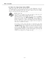
If the printing quality has degraded due to a change in the head gap, see
Chapter
3: 3.3
Head Gap Adjustment on Page
to adjust the head gap.
REFERENCE
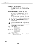
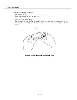
Lubrication points
Do
not touch the greased parts of the carriage guide frame, carriage shaft, idler roller
and
parts. Doing so will wipe off the grease which has been applied for the smooth
operation of the printer unit.
Do not apply grease to any unspecified parts and surfaces. If grease is on
the purge section’s rubber cap or the wiping assembly’s blade, it may cause
the
cartridge’s nozzles to clog, rendering the BJ cartridge unusable.
NOTE
Also. do not use any
other than the specified type. Using a different
type of grease may dissolve deform plastic parts.
-
-
If you accidentally
greased surface, reapply the grease. See the
PARTS CATALOG
(provided separately).
REFERENCE
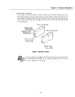
spurs
During
servicing, be
not to
or deform the spur assembly’s spur tips. If the
spur tips
deformed, the
of
paper coming into contact after the printing increases,
causing
vertical
black stripes on
paper.
Carriage
ribbon cable assembly
cable more than is necessary. Doing so may
disrupt the cable’s continuity and prevent the printing signals to be sent properly to the
cartridge.
Power off during printing
During servicing, do not
the
cord during a printing operation while
the cartridge is being replaced. Otherwise, the cartridge will stop at a position
the ink nozzles cannot be
by the rubber cap. The ink may then dry and clog
the nozzles. During servicing, be sure
cartridge is properly positioned for nozzle
l-44
Содержание C5000 - MultiPASS Color Inkjet Printer
Страница 1: ...MultiPASS C5000 SERVICE MANUAL Canon ...
Страница 5: ...REVISION I CONTENT 0 I Original ...
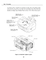
Страница 26: ...Chapter 7 General Description 3 1 External View Front View Figure 1 3 External View 1 l 11 ...
Страница 27: ...Part 1 Facsimile Rear View Inside the Printer Cover Figure 1 4 External View 2 1 12 ...
Страница 28: ...Part 7 Facsimile 3 2 Operation Panel The Operation Panel Document feed lever 0 0 0 0 1 14 ...
Страница 34: ...Part 1 Facsimile ...
Страница 36: ...Part 7 Facsimile r w Units mm r 0 4 0 0 Figure l 13 Dimensions l 22 ...
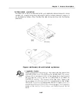
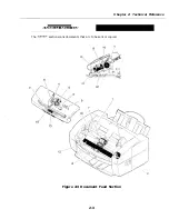
Страница 57: ...Chapter 1 General Description 5 3 3 Print assembly BJ Cartridge _ Figure l 20 Print Assembly Precautions l 43 ...
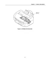
Страница 65: ...Chapter 1 General Description Waste Ink absorber Figure 1 23 Waste Ink Absorber 1 51 ...
Страница 92: ...Part 7 Facsimile Figure 2 18 Printing Signals HQ Mode 2 24 ...
Страница 93: ...Chapter 2 Technical Refereno 6 1 Component Block Diagram Figure 2 19 Block Diagram 2 25 ...
Страница 150: ...Part 1 Facsimile Figure 3 28 Print Pattern Sample 3 48 ...
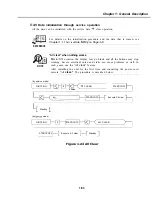
Страница 164: ... Part 1 Facsimile a 2 System dump list a STSrn DlYP LIST t t tf t Figure 3 35 System Dump List l 2 3 62 ...
Страница 184: ...Part 1 Facsimile U Vertical alignment Correction l l l l 3 7 ...
Страница 194: ...Part 2 Printer 3 1 Interface Connector 81 DIRECTIONAL PARALLEL PORT Figure 1 4 Interface Connector l 10 ...
Страница 212: ...Chapter 3 Maintenance Service See Part 1 Facsimile Chapter 3 Maintenance Service for details REFERENCE 3 1 ...