background image

6226 Netherhart Road, Mississauga, Ontario, L5T 1B7 

99-0212 

Rev. 00 


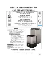
INSTALLATION OPERATION 

AND SERVICE MANUAL 


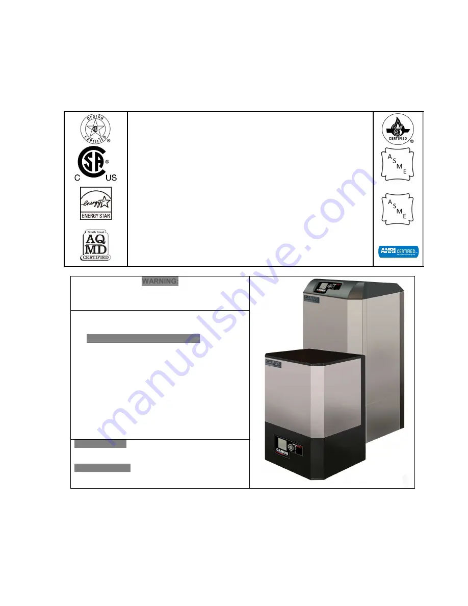
GAS FIRED WALL HUNG & FLOOR MOUNT RESIDENTIAL 

COMMERCIAL STAINLESS STEEL BOILERS


DynaMax HS SERIES 


HYDRONIC HEATING 

Models; DMH081, 101, 151, 201, 251, 
 211, 261, 291, 391, 501, 601, 701, 801


HOT WATER SUPPLY 

Models

;

 DMW082 ,102, 152, 202, 252,  

212, 262, 292, 392, 502, 602, 702, 802 


COMBINATION HEATING/HOT WATER SUPPLY 

Models

;

 DMC083, 103, 153, 203, 253,  

213, 263, 293, 393, 503, 603, 703, 803


HLW 


WARNING: 

If the information in these instructions is not followed 
exactly, a fire or explosion may result causing property 
damage, personal injury or death 


Do not store or use gasoline or other flammable 
vapours and liquids in the vicinity of this or any 
other appliance. 
WHAT TO DO IF YOU SMELL GAS 

o


Do not try to light any appliance, 

o


Do not touch any electrical switch; do not 
use any phone in your building, 

o


Immediately call your gas supplier from a 
neighbour’s phone. Follow the gas 
supplier’s instructions, 

o


If you cannot reach your gas supplier, call 
the fire department. 

Qualified installer, service agency or the 
gas supplier must perform installation and 
service. 

 
To the Installer: After installation, these instructions 
must be given to the end user or left on or near the 
appliance. 
To the End User: This booklet contains important 
information about this appliance. Retain for future 
reference.  

CAMUS   HYDRONICS   LTD. 

Содержание DynaMax DMH081

Страница 1: ...mage personal injury or death Do not store or use gasoline or other flammable vapours and liquids in the vicinity of this or any other appliance WHAT TO DO IF YOU SMELL GAS o Do not try to light any a...

Страница 2: ......

Страница 3: ...NATION AND AIR INLET CLEARANCES 10 2 5 1 Sidewall Venting 10 2 5 2 Sidewall Air Inlet 10 2 5 3 Sidewall Concentric Vent Air 11 2 6 Vertical Direct Venting 11 PART 3 GAS CONNECTION 13 3 1 GAS CONNECTIO...

Страница 4: ...NANCE 51 9 1 EXAMINE THE VENTING SYSTEM 51 9 2 VISUALLY CHECK MAIN BURNER FLAMES 51 9 3 CLEANING BOILER HEAT EXCHANGER 51 9 4 CONDENSATE TREATMENT 52 9 5 IGNITER AND FLAME SENSOR ELECTRODES 52 9 6 CHE...

Страница 5: ...0 12 LOCAL REMOTE SWITCH 59 10 13 MODBUS LOCAL SWITCH 59 10 14 APPLIANCE 59 PART 13 PIPING DIAGRAMS 60 PART 14 EXPLODED VIEW PARTS LIST 65 PART 15 ELECTRICAL DIAGRAMS 73 15 1 DM 80 299 INTERNAL WIRING...

Страница 6: ...QUENCE OF OPERATION 1 Power switch is placed in the ON position 2 Minimum 120 VAC 60Hz single phase 15A circuit is supplied to the DynaMax HS field connection board 3 24Vac power is supplied to the Dy...

Страница 7: ...bustion and proper venting 1 6 INSTALLATION CODES The equipment shall be installed in accordance with those installation regulations enforced in the local area where the installation is to be made The...

Страница 8: ...pecting and cleaning the heat exchanger and vent pipe 1 Turn off electrical power and main manual gas shut off and allow appliance to cool down 2 Remove the vent pipe at connection to heat exchanger a...

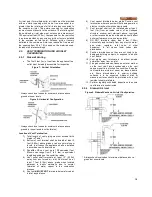
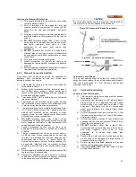
Страница 9: ...ndoors where it is protected from exposure to wind rain and weather The appliance designed for outdoor installation Outdoor Models must be installed outdoors Always consider the use of a shelter such...

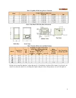
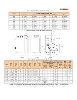
Страница 10: ...ifications Model Depth Dim A in Dim B in Equivalent Length of Vent Air Intake Pipes at Recommended Diameter in Water Connection at Boiler in NPT Gas Connection at Boiler in NPT Over 25 and up to 100 O...

Страница 11: ...t Recommended Diameter in Water Conn at Heater in NPT Gas Conn at Boiler in NPT Category IV CAT II Comb Vents Over 25 and up to 100 Over 15 and up to 25 Up to 15 210 36 22 3 4 14 1 4 23 24 1 4 34 1 4...

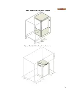
Страница 12: ...7 Figure 5 DynaMax HS Wall Hung Service Clearances Figure 6 DynaMax HS Floor Mount Service Clearances...

Страница 13: ...tive vent system is disconnected for any reason the flue must be reassembled and resealed according to the vent manufacturer s instructions Do not use an existing chimney as a raceway if another appli...

Страница 14: ...onal designer acceptable to the authority having jurisdiction 1 The DynaMax HS Floor Mount boiler may be vented as a Category II appliance using sealed vent suitable for a condensing appliance 2 3 1 A...

Страница 15: ...nterline radius 4 Vent outlet shall terminate at least 12 0 30m away from any forced air inlet Vent must be at least 7 feet 2 15m above grade when located adjacent to public walkways due to normal for...

Страница 16: ...dence 7 Position termination so they are not likely to be damaged by foreign objects or exposed to a build up of debris 8 Flue gas condensate can freeze on exterior walls or on the vent cap Frozen con...

Страница 17: ...Concentric Vent Vertical Venting CAUTION Do not operate appliance with the terminal cap removed as this may result in the recirculation of flue products Water may also flow into the combustion air pip...

Страница 18: ...the size of the connection on the appliance Sizing based on Table 8 is recommended depending on model Before operating the appliance the complete gas train and all connections must be tested using so...

Страница 19: ...ess The valve is a 1 1 negative pressure gas valve The valve performs the functions of a pressure regulator safety shutoff and air gas ratio control Full closing of the valve seat occurs in less than...

Страница 20: ...If the appliance is installed above radiation level it must be provided with a low water cut off device at the time of appliance installation available from Camus Some local codes require the install...

Страница 21: ...ntable heat exchanger damage Table 10 Minimal System Pipe Size Input BTU hr Water Size NPT in 80 000 1 100 000 1 150 000 1 199 000 1 1 4 250 000 1 1 4 299 000 1 1 2 399 000 2 500 000 2 600 000 2 700 0...

Страница 22: ...99 000 12 6 7 2 10 8 5 8 250 000 15 8 11 5 13 5 8 7 299 000 18 9 9 3 16 2 7 0 399 000 25 2 8 4 21 6 6 3 500 000 31 5 9 2 27 0 6 9 600 000 38 8 17 5 32 0 11 8 700 000 45 3 18 2 40 0 14 4 800 000 51 8 2...

Страница 23: ...ted every six months The normally open switch contact of the low water cutoff is to be wired in series with the flow switch This can be wired into the DynaMax HS terminal labelled Flow Switch CAUTION...

Страница 24: ...be horizontal for at least an inch to ensure sufficient electrical conductivity 5 2 HIGH LIMIT A manual reset fail safe high limit aqua stat control is inside the appliance and the control bulb is in...

Страница 25: ...utdoor sensor fault 105 Flame detected out of sequence 106 Flame lost in Main Flame Establishing Period MFEP 107 Flame lost early in run 108 Flame lost in run 109 Ignition failed 112 Pilot test flame...

Страница 26: ...ay between stages minimum on time per stage minimum off time per stage Flame failure signal Error message display in text Manual override of boiler input rate for combustion Pump exercising feature ru...

Страница 27: ...shooting information on the diagnostic screen Figure 25 Diagnostic Screen PARAMETER DESCRIPTION Boiler pump Pump A Auxilary Pump Pump B 3 way valve diverter operation DHW Pump Pump C Additional contac...

Страница 28: ...int Modulates on boiler inlet sensor default Heat demand is generated when Remote Operator is closed 1 Place both toggle switches to LOCAL 2 Press and select Login 3 Select Quick Start 4 Select CH Set...

Страница 29: ...switches to LOCAL 2 Press and select Login 3 Select Advanced Setup 4 Select CH Config 5 Select Outdoor Reset Config 6 Select Outdoor Reset and Press and select Enable 7 Set Max outdoor temp Warm weath...

Страница 30: ...Connect Outdoor Sensor to J3 ECOM connector 4 Place both toggle switches in LOCAL 5 Press and select Login 6 Select Advanced Setup 7 Select CH Config 8 Select Outdoor Reset Config 9 Select Outdoor Res...

Страница 31: ...structions Boiler operates with variable setpoint determined by 4 20mA incoming signal Modulates on header sensor Heat demand is generated when Remote Operator is closed and 4 20mA or 0 10Vdc signal i...

Страница 32: ...CAL 2 Press and select Login 3 Select Advanced Setup 4 Select DHW Config Inlet Sensor operation 5 Select Demand switch Sensor only and Press 6 Select Mod sensor Inlet and Press go to step 7 DHW Stat o...

Страница 33: ...eat demand is generated when Remote Operator is closed DHW Sensor Stat if required 1 Place both toggle switches in LOCAL 2 Press and select Login 3 Select Advanced Setup 4 Select DHW Config 5 Select D...

Страница 34: ...address 1 7 Verify MB2 Modbus address 1 8 Select Lead Lag Config 9 Select Lead Lag Master Config 10 Select Master enable Enable Fixed Setpoint operation 11 Select Setpoint and enter desired setpoint u...

Страница 35: ...ches in LOCAL 2 Press and select Login 3 Select Advanced Setup 4 Select System 5 Select System ID Access 6 Select MB1 Modbus address 2 To be in sequential order 7 Select MB2 Modbus address 2 To be in...

Страница 36: ...mp src and Press 6 Select S5 and Press Master Boiler 7 Place both toggle switches in LOCAL 8 Press and select Login 9 Select Advanced Setup 10 Select Lead Lag Config 11 Select Lead Lag Outdoor Reset 1...

Страница 37: ...t after Interstage delay 2 minutes a lag boiler will be brought online and will also fire at the base load rate specified Modulation of boilers will only occur after all boilers in the Lead Lag system...

Страница 38: ...1 equalize run time default Add stage error threshold 718 0 130 o C Default 5 o F 3 o C Add stage inter stage delay 722 0 64800 seconds Default 120 seconds Drop stage threshold 727 0 130 o C Default 5...

Страница 39: ...23 3 233 0 17 8 178 10 12 2 122 20 6 7 67 30 1 1 11 40 4 4 44 50 10 0 100 60 15 6 156 70 21 1 211 80 26 7 267 90 32 2 322 100 37 8 378 110 43 3 433 120 48 9 489 130 54 4 544 140 60 0 600 150 65 6 656...

Страница 40: ...n LOCAL 2 Press and select Login 3 Select Advanced Setup 4 Select Burner Control Ignition 5 Select Adjustable lightoff rate and enter desired lightoff rate using 5 way control and press Adjust stack l...

Страница 41: ...iption Programming Instructions To view burner run time pump cycles for maintenance and service purposes 1 Place both toggle switches in LOCAL 2 Press and select Login 3 Select Advanced Setup 4 Select...

Страница 42: ...e deposit on the sensor rod must be removed with steel wool DO NOT use sand paper or grit cloth since this will contaminate the metal surface 7 3 COMBUSTION AIR FAN DynaMax HS uses a modulating air fa...

Страница 43: ...from the system Verify that wiring is correct Flame Failure Pressing the manual OK button on the DynaMax HS Control Panel to restart the ignition sequence The boiler has failed to ignite the burner af...

Страница 44: ...ocedure Clean or replace the burner if required Air in the piping system Purge all air from the piping system Incorrect igniter gap Check that spark gap is 9 64 Auto Reset High Limit Trips The outlet...

Страница 45: ...are wired correctly Measure the resistance of the sensors 10k sensors Replace the sensor if necessary Fan Not Turning Fan refuses to rotate Alert 122 123 128 129 130 131 132 Check fan power wires Fan...

Страница 46: ...Burner switch turned OFF 30 Burner switch turned ON 47 Flame rod to ground leakage 49 Abnormal 24Vac voltage 50 Modulation Fault 61 Anti short Cycle 62 Fan speed not proved 67 Interlock Off safety cir...

Страница 47: ...turn at a time NO Verify gas valve is being powered by ignition control Check ignition speed is between 2500 to 3000 RPM using System Monitor NO Adjust ignition speed to 3000 RPM YES YES Burner light...

Страница 48: ...tripped optional To identify the safety that is open set the multimeter to Vac and measure the voltage from one contact to ground The contacts produce a 24Vac when the circuit is closed Is vent and o...

Страница 49: ...closed Is pump powered NO Check pump wiring and pump delay relay YES Is there a current transformer NO Check operation of paddle style flow switch installed on outlet of DynaMax HS YES Use meter to v...

Страница 50: ...150 o F is selected and PVC venting is used the setpoint must be reduced to below 150 o F to avoid nuisance flame failures If a setpoint greater than 150 o F is required venting with CPVC AL29 4C 316...

Страница 51: ...rod Is Flame sensor plug secure NO Fasten flame sensor plug securely to flame sensor wire and check for corrosion deposits at wire terminals YES Check continuity of flame sensor wire from flame sensor...

Страница 52: ...x HS must be firing before proceeding DM 080 250 260 Figure 56 Venturi Gas Valve Assembly To adjust the high fire setting 1 Press the button 2 Select Test and press 3 Select Forced Rate and press 4 Se...

Страница 53: ...1 Press the button 2 Select Test and press 3 Select Forced Rate and press 4 Select Set High Fire Locate the input adjustment screw on the top side of the gas valve Turn the screw 1 8 turn in either w...

Страница 54: ...uction of air flow to the burner Yellow Flames Yellow flames can be caused by blockage of primary air flow to the burner or excessive gas input This condition MUST be corrected immediately If improper...

Страница 55: ...eplace neutralizer medium as required There are several factors affecting amount of condensation created by the appliance however for rough approximation use Condensation Volume US Gallon Hr Input MBH...

Страница 56: ...re when removing and handling the burner Sharp objects or impact may damage or tear the metal fiber surface rendering the burner unfit for service 9 8 REMOVAL OF COMBUSTION CHAMBER LINING The combusti...

Страница 57: ...an be provided by using hydronic system antifreeze Follow the manufacturer s instructions DO NOT use undiluted or automotive type antifreeze Shut down and draining If for any reason the unit is to be...

Страница 58: ...used The expansion tank must be installed close to the boiler and on the suction side of the system pump appliance Inlet to ensure proper operation Caution This appliance should not be operated at les...

Страница 59: ...y loop 2 Check system for any water leaks 3 Check system for installation of glycol or water treatment where required Where glycol has been used to maintain the temperature rise across the appliance c...

Страница 60: ...se 4 Be sure all valves are open between the hot water heater and the storage tank Ensure that all ball valves are fully ported 5 Check the pump to be sure it is running properly and that the pump mot...

Страница 61: ...emain the same Lead lag Lead lag setpoint Add stage Error threshold AND Lead lag Lead lag setpoint Drop stage Error threshold 3 A boiler should stop Lead lag Lead lag setpoint Drop stage Error thresho...

Страница 62: ...Local Remote switch is independent of the 4 20mA 2 10Vdc signal 10 13 MODBUS LOCAL SWITCH The Modbus Local Switch mounted on the terminal board is designed to relay the signal to the boiler display lo...

Страница 63: ...eader to minimize induced flow through zones 2 Separate boiler loop as shown is recommended for system piping greater than 50 equivalent feet Pressure Reducing Valve Pressure Gauge Ball Valve Air Sepa...

Страница 64: ...Valve Air Separator Expansion Tank Zone Circulator Flow Check Valve DynaMax HS Boiler Temperature Pressure Gauge Drain Union Anti scald Mixing Valve Note 1 Size main header to minimize induced flow th...

Страница 65: ...Separator Expansion Tank Zone Circulator Flow Check Valve DynaMax HS Boiler Temperature Pressure Gauge Drain Union Anti scald Mixing Valve Note 1 Size main header to minimize induced flow through zone...

Страница 66: ...63 Figure 34 Single Boiler Hydronic Heating Direct Storage Tank Zoned Piping Arrangement Cold Water In DHW Sensor Union Direct DHW Tank Anti Scald Mixing Valve Cold Water In Hot Water Out...

Страница 67: ...Flow Check Valve DynaMax HS Boiler Master M1 Temperature Pressure Gauge Drain Union DynaMax HS Boiler Slave S2 System Sensor Note 1 Size main header to minimize induced flow through zones 2 Location...

Страница 68: ...65 PART 14 EXPLODED VIEW PARTS LIST DYNAMAX HS WALL HUNG...

Страница 69: ...66 DYNAMAX HS FLOOR MOUNT...

Страница 70: ...ge Nuts GM10 05 012 X 5 Igniter GM10 35 108 01 X X X X X X X X X X GM10 35 161 01 X X X 6 Flame Sensor GM10 35 109 01 X X X X X X X X X X GM10 35 162 00 X X X 7 Igniter Flame Sensor Screws GM10 05 020...

Страница 71: ...X VCZND6100 U X VBN3EM3POX X X VBN3FP3POX X X X 18 High Limit TCL085A X TCL110A X 19 Turn Lock Wall Hung X Floor Mount X 20 Wall Mount Back Panel 14 5402 X X X 14 5402 250 X X 21 Wall Mount Front Bot...

Страница 72: ...X 14 5505 60 75 X X X 43 Side Panel Right 14 5506 20 25 X X 14 5506 X X X 14 5506 60 75 X X X 44 Side Panel Left 14 5507 20 25 X X 14 5507 X X X 14 5507 60 75 X X X 45 Front Panel Bottom 14 5508 X X...

Страница 73: ...ange with 3 Street Elbow 44 0009 X 4 Air Intake Box 14 5551 X X 5 Air Intake Box 14 5546 X 69 3 Air Intake Adapter 44 0010 X 4 Air Intake Adapter 14 5559 X X 5 Air Intake Adapter 14 5556 X 70 Condensa...

Страница 74: ...X X X X 91 DynaMax HS Fan Discharge Orifice 14 0377 80 X X 14 0377 100 X 14 0377 250 X X 92 Expandable Air Inlet Adapter w o Pressure Test Point 14 0378 X X X X X 93 Expandable Air Inlet Adapter 1056...

Страница 75: ...t Mixing Chamber Gasket 33 0036 X X X X X X X 33 0037 X X X X X X X X X 33 0038 X 33 0043 X X X 33 0057 X X X 106 Air Inlet Gasket 33 0069 X X X 107 Current Transformer Combination Models only RIBXRA...

Страница 76: ...73 PART 15 ELECTRICAL DIAGRAMS 15 1 DM 80 299 INTERNAL WIRING DIAGRAM...

Страница 77: ...74 15 2 DM 399 800 INTERNAL WIRING DIAGRAM...

Страница 78: ...75...

Страница 79: ...ough sequential Modbus addresses Connect the system sensor to the master boiler The master boiler will use the water temperature in the primary loop to control the operation of the lead lag setup If o...

Страница 80: ...s C2 Vdc Display J4 2 3 DHW Pump 1 6hp 4 24Vac or 115Vac for pump contact 5 6 3 way diverter valve 7 Boiler pump contact 10 24Vac return 12 Ground J5 1 Interlock 2 Gas Valve contact J6 1 Blocked Flue...

Страница 81: ...excluded however if caused by appliance operation at large changes exceeding 150 F between the water temperature at inlet and appliance temperature or operating at temperatures exceeding 210o F BURNE...

Страница 82: ...uilt water heaters and heating boilers as well as a into every single unit For more information supplier of specialty HVAC products Our service line is open 24 hours 7 days a week on our innovative pr...

Отзывы: