4-7
4.5 Trimming
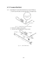
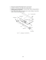
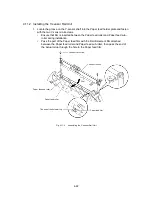
Mechanism
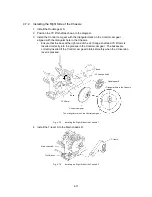
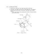
4.5.1
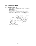
Assembling the Trimming Assy
1. Align the Leaf switch assy TRI with the T-cutter assy boss hole and attach it with the
Leaf switch TRI screw.
2. Fasten the harness to the hooks.
Engage the harness into the hook under the Cassette holder, then fix it with tape on
the two marked areas (Chassis B front face and Chassis R inside surface).
3. Align the T-cutter assy with the boss holes and install it with the T-cutter screw.
T-cutter screw
Leaf switch TRI screw
Leaf switch TRI assy
T-cutter assy
The bottom face of
cassette holder
Leaf switch TRI harness
Fig. 4.5-1
Assembling the Trimming Assy
Содержание LX-1200
Страница 1: ...SERVICE MANUAL MODEL LX 1200 LX 300 ...
Страница 2: ...COOL LAMINATOR SERVICE MANUAL MODEL LX 1200 LX 300 ...
Страница 5: ...Chapter 1 SPECIFICATIONS ...
Страница 9: ...Chapter 2 MECHANISMS ...
Страница 20: ...Chapter 3 DISASSEMBLY PROCEDURES ...
Страница 58: ...Chapter 4 ASSEMBLY PROCEDURES ...
Страница 105: ...Chapter 5 ELECTRONIC CONTROLLERS ...
Страница 127: ...Chapter 6 MAINTENANCE ...
Страница 149: ...Chapter 7 TROUBLESHOOTING ...
Страница 174: ...APP 1 Appendix Main PCB Circuit Diagram ...
Страница 175: ...July 2000 86S006BE0 Printed in Japan ...

