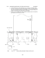
6-19
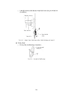
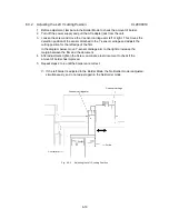
6.3.2 Adjusting the Left Y-cutting Position CL2000010
1. Before adjustment, laminate in the Border Mode to check the amount of border.
2. Turn off the power supply and pull the AC adapter jack from the unit.
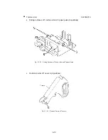
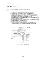
3. Loosen the screw and move the Y-sensor carriage arm left or right. This moves the
detection position of the sensor attached to the Y-sensor carriage and adjusts the
cutting position for the left edge of the film.
In the diagram below, move Y-sensor carriage arm to the right to increase the
margin between the film and the document.
4. After adjustment, tighten the Screw. Laminate a test document to check if the
amount of border has improved.
5. Repeat steps 2 to 4 until the borders are correct.
∗
If the left border is adjusted in the Border Mode, the No Border mode is adjusted
simultaneously, so do not adjust again in the No Border mode.
Screw
Y-sensor carriage arm
Y-cutter arm
Y-sensor carriage
Fig. 6.3-2
Adjusting the Left Y-cutting Position
Содержание LX-1200
Страница 1: ...SERVICE MANUAL MODEL LX 1200 LX 300 ...
Страница 2: ...COOL LAMINATOR SERVICE MANUAL MODEL LX 1200 LX 300 ...
Страница 5: ...Chapter 1 SPECIFICATIONS ...
Страница 9: ...Chapter 2 MECHANISMS ...
Страница 20: ...Chapter 3 DISASSEMBLY PROCEDURES ...
Страница 58: ...Chapter 4 ASSEMBLY PROCEDURES ...
Страница 105: ...Chapter 5 ELECTRONIC CONTROLLERS ...
Страница 127: ...Chapter 6 MAINTENANCE ...
Страница 149: ...Chapter 7 TROUBLESHOOTING ...
Страница 174: ...APP 1 Appendix Main PCB Circuit Diagram ...
Страница 175: ...July 2000 86S006BE0 Printed in Japan ...

