7-6
2
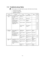
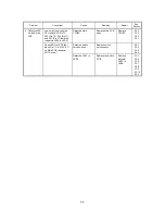
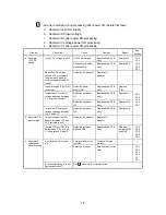
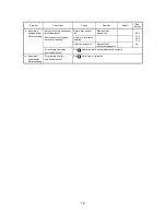
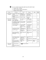
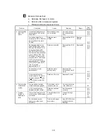
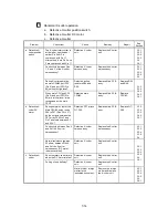
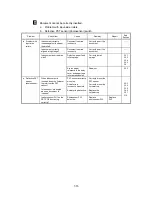
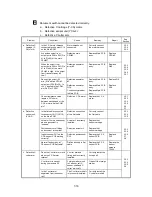
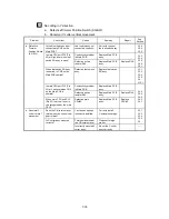
Nothing happens when switches are pressed.
a. Defective switch or push switch on the Switch PCB.
b. Defective LED on the Switch PCB.
Problem Check
Item
Cause Remedy
Repair
See
Section
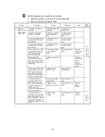
Is Switch PCB correctly
mounted?
Defective Switch PCB
mounting.
Correctly mount
Switch PCB.
Is switch harness assy
correctly connected?
Defective connection
of switch harness
assy.
Correctly connect
switch harness
assy.
Is the white lead connector
connected to CN1 on the
Switch PCB?
Push switch assy not
connected.
Correctly connect
the push switch
assy.
Is the red lead connector
connected to CN2 on the
Switch PCB?
Push switch assy not
connected.
Correctly connect
the push switch
assy.
When switch SW1 to SW6
is pressed on the Switch
PCB, does the switch
become conducting?
Conductivity problem
in switch SW1 to
SW6.
Replace the Switch
PCB.
Replace
switch SW1
to SW6.
When push switch
RSW1
•
RSW2 is shorted,
does the connector on the
push switch assy become
conducting?
Defective push switch
assy.
Replace
push switch
assy 1.
Replace
push switch
assy 2.
When switch SW1 to SW6
is pressed on the Switch
PCB or the push switch
assy is shorted, can the
conductivity be checked at
CN16 on the main CPU?
Defective switch
harness assy.
Replace switch
harness assy.
3.3.3
3.3.4
3.3.5
3.3.7
3.3.8
3.3.9
3.3.10
Conductivity problem
in Main PCB.
Replace Main PCB
assy.
If conductivity can be
checked at CN16 on the
main CPU when switch
SW1 to SW4 is pressed or
the push switch assy is
shorted, can the
conductivity be checked at
the main CPU ports?
Defective series
resistor on main CPU.
Replace Main PCB
assy.
Replace
series
resistor.
a. Defective
switch or push
switch on the
Switch PCB
If conductivity can be
checked at the main CPU
ports when switch SW1 to
SW4 is pressed or the push
switch assy is shorted, is
this recognized by the main
CPU?
Defective main
CPU#3.
Replace Main PCB
assy.
Replace
CPU#3.
3.3.3
3.3.4
3.3.5
3.5.1
Содержание LX-1200
Страница 1: ...SERVICE MANUAL MODEL LX 1200 LX 300 ...
Страница 2: ...COOL LAMINATOR SERVICE MANUAL MODEL LX 1200 LX 300 ...
Страница 5: ...Chapter 1 SPECIFICATIONS ...
Страница 9: ...Chapter 2 MECHANISMS ...
Страница 20: ...Chapter 3 DISASSEMBLY PROCEDURES ...
Страница 58: ...Chapter 4 ASSEMBLY PROCEDURES ...
Страница 105: ...Chapter 5 ELECTRONIC CONTROLLERS ...
Страница 127: ...Chapter 6 MAINTENANCE ...
Страница 149: ...Chapter 7 TROUBLESHOOTING ...
Страница 174: ...APP 1 Appendix Main PCB Circuit Diagram ...
Страница 175: ...July 2000 86S006BE0 Printed in Japan ...

