2-1
2.1 Mechanical Operating Principles
2.1.1
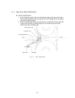
Description of Mechanisms (Border Mode)
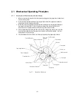
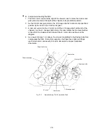
1. When a document is inserted into the paper loading gate, the paper feed rollers feed
it to the driving roller.
2. As the document passes between the paper feed rollers, the paper size detector
determines its size (length and width).
3. When the document passes between the film cartridges it is sandwiched between
the upper and lower films in the compression-feed area, where the films and
document are compressed between the driving roller and sub-roller.
4. The compressed document and film is fed to the cutting area, where it is cut to the
document size detected by the paper size detector with borders added. It is then
transported to the next stage.
5. The laminated document is fed out of the eject gate by the paper eject rollers.
Eject gate
Y-cutter blade
Paper eject roller
X-cutter unit
Paper eject sub-roller
Ejecting area
Sub-roller
Film cartridge
Cutting area
Driving roller
Compression-feed area
Roll film (lower)
Paper feed roller
Paper loading area
Paper length detector
Paper loading gate
Paper width detector
Paper feed
sub-roller
Roll film (upper)
Fig. 2.1-1
Description of Mechanisms
Содержание LX-1200
Страница 1: ...SERVICE MANUAL MODEL LX 1200 LX 300 ...
Страница 2: ...COOL LAMINATOR SERVICE MANUAL MODEL LX 1200 LX 300 ...
Страница 5: ...Chapter 1 SPECIFICATIONS ...
Страница 9: ...Chapter 2 MECHANISMS ...
Страница 20: ...Chapter 3 DISASSEMBLY PROCEDURES ...
Страница 58: ...Chapter 4 ASSEMBLY PROCEDURES ...
Страница 105: ...Chapter 5 ELECTRONIC CONTROLLERS ...
Страница 127: ...Chapter 6 MAINTENANCE ...
Страница 149: ...Chapter 7 TROUBLESHOOTING ...
Страница 174: ...APP 1 Appendix Main PCB Circuit Diagram ...
Страница 175: ...July 2000 86S006BE0 Printed in Japan ...

