5-8
S
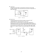
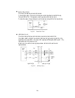
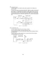
Buzzer Drive Circuit
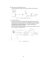
This circuit sounds the piezoelectric buzzer.
To sound the buzzer, the main CPU outputs a 4 kHz squarewave with 50% duty
from port DV0 (P13). This signal is used to generate the buzzer sound.
To stop the buzzer, the port status is set to High level using R69 in the input mode.
Fig. 5.3-4
Buzzer Drive Circuit
S
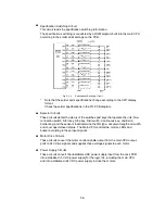
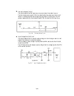
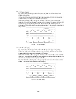
LED Drive Circuit
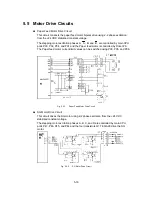
This circuit drives the four LED indicators mounted on the Switch PCB.
The LED4, LED2, and LED1 are directly driven by the high-current ports P30, P33,
and P34 on the main CPU. The main CPU output port P52 lights LED3 via Q1. The
LED lights when the output is Low.
When not lit, the LED is in the high-impedance status and the port level is
indeterminate.
Fig. 5.3-5
LED Drive Circuit
Содержание LX-1200
Страница 1: ...SERVICE MANUAL MODEL LX 1200 LX 300 ...
Страница 2: ...COOL LAMINATOR SERVICE MANUAL MODEL LX 1200 LX 300 ...
Страница 5: ...Chapter 1 SPECIFICATIONS ...
Страница 9: ...Chapter 2 MECHANISMS ...
Страница 20: ...Chapter 3 DISASSEMBLY PROCEDURES ...
Страница 58: ...Chapter 4 ASSEMBLY PROCEDURES ...
Страница 105: ...Chapter 5 ELECTRONIC CONTROLLERS ...
Страница 127: ...Chapter 6 MAINTENANCE ...
Страница 149: ...Chapter 7 TROUBLESHOOTING ...
Страница 174: ...APP 1 Appendix Main PCB Circuit Diagram ...
Страница 175: ...July 2000 86S006BE0 Printed in Japan ...


