4-3
4.3 Main Chassis B
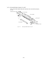
4.3.1
Installing the Main Chassis L, R, and F
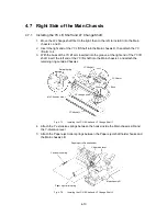
1. Insert the lugs on the Main chassis B and F into the square holes in the Main
chassis L and R. Assemble the Main chassis L, R, F, and B with the ten Side
chassis screws (five each side).
2. Attach the Edging saddle to the Main chassis B.
Main chassis L
Main chassis B
Edging saddle
Side chassis screws
Main chassis F
Main chassis R
Side chassis screws
Fig. 4.3-1
Installing the Main Chassis L, R, and F
4.3.2
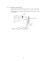
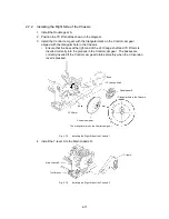
Installing the ENC Sensor PCB
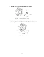
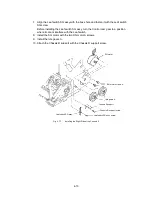
Align the boss on the ENC sensor PCB assy. Attach the ENC sensor PCB assy to the
Cassette holder with the ENC sensor PCB screw.
Pass the ENC sensor harness through the hole in the Cassette holder.
Boss
ENC Sensor PCB assy
ENC Sensor
PCB screw
Fig. 4.3-2
Installing the ENC Sensor PCB
Содержание LX-1200
Страница 1: ...SERVICE MANUAL MODEL LX 1200 LX 300 ...
Страница 2: ...COOL LAMINATOR SERVICE MANUAL MODEL LX 1200 LX 300 ...
Страница 5: ...Chapter 1 SPECIFICATIONS ...
Страница 9: ...Chapter 2 MECHANISMS ...
Страница 20: ...Chapter 3 DISASSEMBLY PROCEDURES ...
Страница 58: ...Chapter 4 ASSEMBLY PROCEDURES ...
Страница 105: ...Chapter 5 ELECTRONIC CONTROLLERS ...
Страница 127: ...Chapter 6 MAINTENANCE ...
Страница 149: ...Chapter 7 TROUBLESHOOTING ...
Страница 174: ...APP 1 Appendix Main PCB Circuit Diagram ...
Страница 175: ...July 2000 86S006BE0 Printed in Japan ...

