3-29
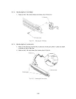
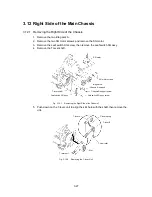
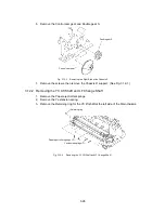
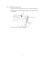
4. Move the YC lift shaft several millimeters toward the right side of the Main chassis
and remove the YC Lift arm.
YC lift arm
YC lift shaft
LF lift arm
Fig. 3.12-5
Removing the YC Lift Shaft and LF Change Shaft 2
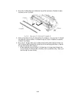
5. Remove the left end of the YC lift shaft from the Chassis L. Remove the YC lift shaft
by pulling the right end of the YC lift shaft through the hole in Chassis R toward the
middle of the chassis.
6. Move the LF change shaft several millimeters toward the Main chassis R. Remove
the LF change shaft by pulling the right end of the shaft through the hole in Chassis
R toward the middle of the chassis.
∗
When pulling the right end of the YC lift shaft and LF change shaft through the
hole in Chassis R, tilt the shafts so that they can be pulled smoothly. Never pull
them through the hole forcibly.
Содержание LX-1200
Страница 1: ...SERVICE MANUAL MODEL LX 1200 LX 300 ...
Страница 2: ...COOL LAMINATOR SERVICE MANUAL MODEL LX 1200 LX 300 ...
Страница 5: ...Chapter 1 SPECIFICATIONS ...
Страница 9: ...Chapter 2 MECHANISMS ...
Страница 20: ...Chapter 3 DISASSEMBLY PROCEDURES ...
Страница 58: ...Chapter 4 ASSEMBLY PROCEDURES ...
Страница 105: ...Chapter 5 ELECTRONIC CONTROLLERS ...
Страница 127: ...Chapter 6 MAINTENANCE ...
Страница 149: ...Chapter 7 TROUBLESHOOTING ...
Страница 174: ...APP 1 Appendix Main PCB Circuit Diagram ...
Страница 175: ...July 2000 86S006BE0 Printed in Japan ...

