4-22
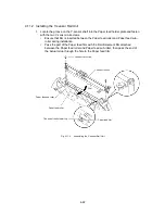
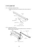
4.11.2 Installing the Y-sensor Rail Unit
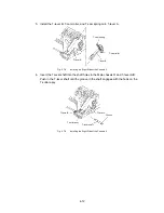
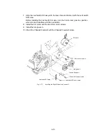
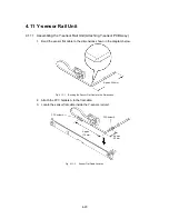
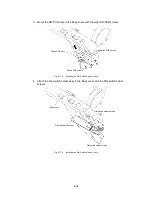
1. Locate the groove on the Y-sensor shaft into the Paper feed holder plate and fasten
with the two Y-sensor rail screws.
∗
Ensure that film is inserted between the Paper feed roller and Paper feed sub-
roller during installation.
∗
Pass the part of the Paper feed film with the Reinforcement film attached
between the Paper feed roller and Paper feed sub-roller, then pass the end of
the Actuator top through the hole in the Paper feed film.
Y sensor rail screw
Y sensor rail unit
Film
Paper feed film
The end of the Actuator top
Paper feed roller
Paper feed sub roller
Fig. 4.11-4
Assembling the Y-sensor Rail Unit
Содержание LX-1200
Страница 1: ...SERVICE MANUAL MODEL LX 1200 LX 300 ...
Страница 2: ...COOL LAMINATOR SERVICE MANUAL MODEL LX 1200 LX 300 ...
Страница 5: ...Chapter 1 SPECIFICATIONS ...
Страница 9: ...Chapter 2 MECHANISMS ...
Страница 20: ...Chapter 3 DISASSEMBLY PROCEDURES ...
Страница 58: ...Chapter 4 ASSEMBLY PROCEDURES ...
Страница 105: ...Chapter 5 ELECTRONIC CONTROLLERS ...
Страница 127: ...Chapter 6 MAINTENANCE ...
Страница 149: ...Chapter 7 TROUBLESHOOTING ...
Страница 174: ...APP 1 Appendix Main PCB Circuit Diagram ...
Страница 175: ...July 2000 86S006BE0 Printed in Japan ...

