5-20
S
+5V Power Supply
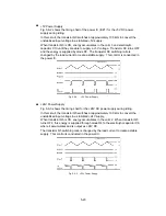
Fig. 5.6-2 shows the timing chart of the power IC (IC#1) for the +5V DC power
supply during idling.
In this circuit, the transistor Q3 switches at approximately 100 kHz to convert the
unstabilized input voltage to a stab5V supply.
When transistor Q3 is ON, energy accumulates in the coil L3 and electrolytic
capacitor C10 until they are able to supply a +5V voltage. Transistor Q3 turns OFF
and the energy is supplied by diode D3. The transistor Q3 switching ratio is
changed by the load current to create a stable supply. This control is conducted in
the power IC.
Fig. 5.6-2
+5V Power Supply
S
+24V Power Supply
Fig. 5.6-3 shows the timing chart for the +24V DC power supply during idling.
In this circuit, the transistor Q5 switches at approximately 100 kHz to convert the
unstabilized input voltage to a stab24V supply.
When transistor Q5 is ON, energy accumulates in the coil L2. When transistor Q5
turns OFF, this energy is supplied through diode D4 to the electrolytic capacitor C8,
where it accumulates and is output as +24V DC.
The transistor Q5 switching ratio is changed by the load current to create a stable
supply. This control is conducted in the power IC.
Fig. 5.6-3 +24V Power Supply
Содержание LX-1200
Страница 1: ...SERVICE MANUAL MODEL LX 1200 LX 300 ...
Страница 2: ...COOL LAMINATOR SERVICE MANUAL MODEL LX 1200 LX 300 ...
Страница 5: ...Chapter 1 SPECIFICATIONS ...
Страница 9: ...Chapter 2 MECHANISMS ...
Страница 20: ...Chapter 3 DISASSEMBLY PROCEDURES ...
Страница 58: ...Chapter 4 ASSEMBLY PROCEDURES ...
Страница 105: ...Chapter 5 ELECTRONIC CONTROLLERS ...
Страница 127: ...Chapter 6 MAINTENANCE ...
Страница 149: ...Chapter 7 TROUBLESHOOTING ...
Страница 174: ...APP 1 Appendix Main PCB Circuit Diagram ...
Страница 175: ...July 2000 86S006BE0 Printed in Japan ...

