3-33
3.17 Main Chassis B
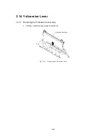
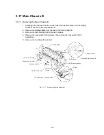
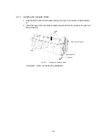
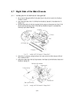
3.17.1 Removing the Main Chassis B
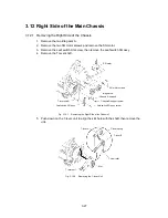
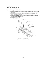
1. Disengage the harness from the hooks under the Cassette holder and the Edging
saddle at the rear of the main chassis B.
2. Remove the Edging saddle from the rear of the main chassis B.
3. Remove the tape holding the ENC sensor harness.
4. Remove the Leaf switch C3/C4 screws, then remove the Leaf switch C3/C4
assemblies.
5. Remove the two Cassette actuators.
Edging saddle
Leaf switch C4 screw
Cassette holder
Rear of the main chassis B
Tape
Harness
ENC sensor
ENC sensor harness
The bottom face of cassette holder
Leaf switch C3 screw
Leaf switch
C4 assy
Leaf switch C3 assy
Cassette actuator
Fig. 3.17-1
Removing the Main Chassis B
Содержание LX-1200
Страница 1: ...SERVICE MANUAL MODEL LX 1200 LX 300 ...
Страница 2: ...COOL LAMINATOR SERVICE MANUAL MODEL LX 1200 LX 300 ...
Страница 5: ...Chapter 1 SPECIFICATIONS ...
Страница 9: ...Chapter 2 MECHANISMS ...
Страница 20: ...Chapter 3 DISASSEMBLY PROCEDURES ...
Страница 58: ...Chapter 4 ASSEMBLY PROCEDURES ...
Страница 105: ...Chapter 5 ELECTRONIC CONTROLLERS ...
Страница 127: ...Chapter 6 MAINTENANCE ...
Страница 149: ...Chapter 7 TROUBLESHOOTING ...
Страница 174: ...APP 1 Appendix Main PCB Circuit Diagram ...
Страница 175: ...July 2000 86S006BE0 Printed in Japan ...


