3-26
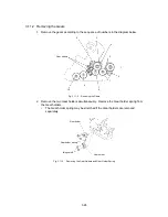
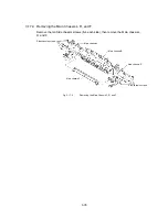
3.11.2 Removing the Gears
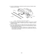
1. Remove the gears according to the sequence of numbers in the diagram below.
5
1
2
Gear holders
7
8
9
10
3
4
6
Fig. 3.11-2
Removing the Gears
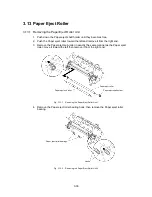
2. Remove the two Gear holders simultaneously. Remove the Gear holder spring from
the Gear holders.
∗
The Gear holder spring may be stretched if the Gear holders are removed
separately.
Gear holder spring
Idle gears B
Gear holder
Gear holder
Fig. 3.11-3
Removing the Gear Holders and Gear Holder Spring
Содержание LX-1200
Страница 1: ...SERVICE MANUAL MODEL LX 1200 LX 300 ...
Страница 2: ...COOL LAMINATOR SERVICE MANUAL MODEL LX 1200 LX 300 ...
Страница 5: ...Chapter 1 SPECIFICATIONS ...
Страница 9: ...Chapter 2 MECHANISMS ...
Страница 20: ...Chapter 3 DISASSEMBLY PROCEDURES ...
Страница 58: ...Chapter 4 ASSEMBLY PROCEDURES ...
Страница 105: ...Chapter 5 ELECTRONIC CONTROLLERS ...
Страница 127: ...Chapter 6 MAINTENANCE ...
Страница 149: ...Chapter 7 TROUBLESHOOTING ...
Страница 174: ...APP 1 Appendix Main PCB Circuit Diagram ...
Страница 175: ...July 2000 86S006BE0 Printed in Japan ...

