width" box defines the width of the filtered frequency band. The value
selected in the example is 1000 Hz. The filter operates within a range
from 400 Hz to 1400 Hz. The strongest filtering is achieved for interfer‐
ing frequencies around 900 Hz
3. Click on "Activate filter type" to activate the filter
Repeat the measurement of the frequency response to check the
effectiveness of the filter settings. Overshoots and phase shifts
should be reduced or should have disappeared completely.
9.4.3
Determining the Kp and Tn parameters
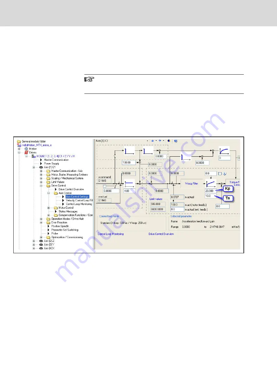
The velocity loop is a PI controller. This PI controller requires determination
of the gain (Kp) and the integral action time (Tn). Enter these parameters in
the "Axis control settings" dialog. The "Frequency response analysis" has to
be started after each change as described above, until the optimal settings
have been found.
Fig. 9-12:
Setting Kp and Tn
Proceed as follows to set the parameters:
1. First set the integral action time Tn = 0. Then slowly increase the gain
Kp. Repeat the measurement of the frequency response of the control‐
ler after each increase. The optimal Kp value has been found if the am‐
plitude response does not show any overshoot of more than 3dB and
the phase shift at the "-3dB" point of the amplitude response is not less
than –-130 degrees at the same time.
Bosch Rexroth AG
DOK-MTXMIC-EASY*******-CO06-EN-P
112/177
IndraMotion MTX micro Easy Setup for Standard Turning and Milling Machines
Commissioning the drives


