M
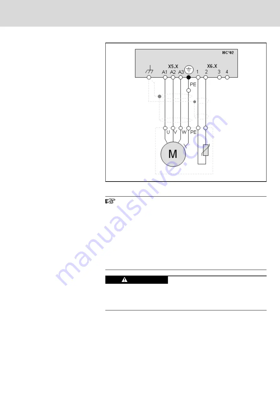
Standard asynchronous motor
Fig. 5-23:
Connecting a standard asynchronous motor to the MTX micro
A temperature monitoring connection point X6 is automatically al‐
located to each motor connection point X5. The following applies:
X5.1 → X6.1, X5.2 → X6.2
●
The cables used for connecting the motor and the tempera‐
ture sensor may only be shielded cables. The shield is con‐
nected via the shield connection points XS2 (tube clips). We
recommend using Rexroth RKL high-performance cables.
●
The maximum length of the connecting cables is 40 m
●
Contacts 3 and 4 of terminal X6 are provided for activating
an external spindle brake. Please comply with the instruc‐
tions in
chapter "Activating an external holding brake" on
Motor activation faults may result in material
damage!
CAUTION
The standard motors must meet the requirements for the "rate of voltage rise
at the motor output" in converter mode. Otherwise, the motor insulation may
be damaged.
Connecting an optional encoder (X8)
The encoder connection point X8 is provided for connection of an optional
encoder, e.g., as a spindle encoder at turning machines.
This interface is designed for connection of a multitude of encoder types:
●
1Vpp, sine wave encoder, with reference track, 12 V and 5 V supply
DOK-MTXMIC-EASY*******-CO06-EN-P
Bosch Rexroth AG
53/177
IndraMotion MTX micro Easy Setup for Standard Turning and Milling Machines
Selecting and connecting the hardware


